
TM 5-3810-300-24&P-3
Fuel Injector
2.1.1
plunger is relieved and the valve spring closes the
chamber and no injection of fuel takes place. With the
needle valve, ending injection.
control rack pushed all the way in (full injection), the
upper port is closed shortly after the lower port has been
A pressure relief passage has been provided in the
covered, thus producing a maximum effective stroke and
spring cage to permit bleed-off of fuel leaking past the
maximum injection.
needle pilot in the tip assembly.
From this no injection position to full injection position
A check valve, directly below the bushing, prevents
(full rack movement), the contour of the upper helix
leakage from the combustion chamber into the fuel
advances the closing of the ports and the beginning of
injector in case the valve is accidentally held open by a
injection.
small particle of dirt. The injector plunger is then
returned to its original position by the injector follower
spring. Figure 4 shows the various phases of injector
General Instructions for Injector Care and Overhaul
operation by the vertical travel of the injector plunger.
The fuel injector is one of the most important and
On the return upward movement of the plunger, the high
precisely built parts of the engine. The injection of the
pressure cylinder within the bushing is again filled with
correct amount of fuel into the combustion chamber at
fuel oil through the ports. The constant circulation of
exactly the right time depends upon this unit. Because
fresh cool fuel through the injector renews the fuel supply
the injector operates against high compression pressure
in the chamber, helps cool the injector and also
in the combustion chamber, efficient operation demands
effectively removes all traces of air which might
that the injector assembly is maintained in first-class
otherwise accumulate in the system and interfere with
condition at all times. Proper maintenance of' the fuel
accurate metering of the fuel.
system and the use of the recommended type fuel filters
and clean water-free fuel are the keys to trouble-free
The fuel injector outlet opening, through which the
operation of the injectors.
excess fuel oil returns to the fuel return manifold and
then back to the fuel tank, is directly adjacent to the inlet
Due to the close tolerances of various injector parts,
opening.
extreme cleanliness and strict adherence to service
instructions is required.
Changing the position of the helices, by rotating the
plunger, retards or advances the closing of the ports and
Perform all injector repairs in a clean, well lighted room
the beginning and ending of the injection period. At the
with a dust free atmosphere. An ideal injector room is
same time, it increases or decreases the amount of fuel
slightly pressurized by means of an electric fan which
injected into the cylinder. Figure 3 shows the various
draws air into the room through a filter. This pressure
plunger positions from no-load to full-load. With the
prevents particles of dirt and dust from entering the room
control rack pulled out all the way (no injection), the
through the doors and windows. A suitable air outlet will
upper port is not closed by the helix until after the lower
remove solvent fumes along with the outgoing air. Also
port is uncovered. Consequently, with the rack in this
provide a source for 110 volt alternating current electric
position, all of the fuel is forced back into the supply
power.
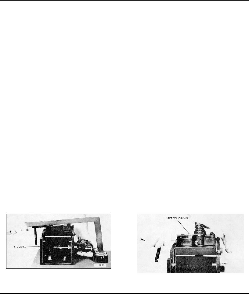
Fig. 8 - Checking Rack and Plunger for Free Movement
Fig. 9 - Removing Injector Follower Stop Pin
Page 160