
TM 5-3810-300-24&P-3
OIL PUMP 4.1
Then rotate the special washer and lock washer
so that the slot in each washer engages the
locating pin (87).
12. Tighten the idler gear bolt so one hex of the bolt
head is over the end of the locating pin (87).
Then bend the lock washer against the flat of the
bolt head.
13. Screw the relief valve plug (37), with copper
gasket (36), into place in the side of the pump
body opposite the inlet opening. Then place the
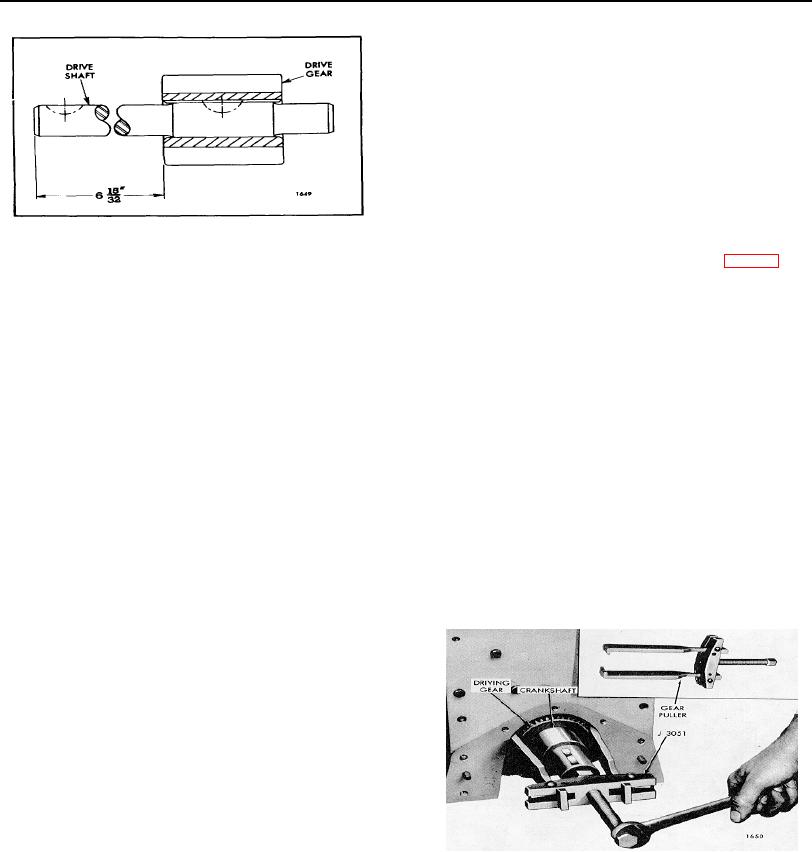
Fig. 7. Oil Pump Drive Shaft and Gear
valve (4) and spring (30) in the bore at the inlet
Assembly-Six Cylinder Engine
side of the pump body as shown in Fig. 2, and
while compressing the spring, start the second
5. If the engine is equipped with a scavenging
relief valve plug (37), with gasket (36), into the
pump, install the oil pump spacer (90) over the
body. Tighten the plugs.
end of the drive and driven gear shafts flush
against the oil pump body.
14. If the cover (28) and gasket (29) were removed
from the pump body, reinstall and secure them
6. Insert two Woodruff keys in the keyway and slide
with the two bolts (78) and lock washers.
the drive gear (gear with keyway) (92) against
the spacer.
The oil pump must turn freely after assembly. Any bind
in the pump must be removed before it is installed on the
7. Slide the driven gear (93) on the driven shaft
engine.
against the spacer.
Remove Oil Pump Driving Gear from Crankshaft
8. Secure the pump cover (21) or scavenging
pump body (91) to the oil pump body with four
bolts (54) and lock washers.
With the oil pan and lubricating oil pump removed, the oil
pump driving gear may be removed from the crankshaft
9. Support the drive gear end of the drive shaft (13)
as follows:
on the bed of an arbor press and insert the
Woodruff key (14) in the keyway of the shaft.
1. Support the front end of engine and remove the
Position the drive-driven gear (49) on the end of
crankshaft front cover (Section 1.3.5).
the drive shaft with the extended hub side up
away from the pump body. Insert a .005" feeler
ribbon between the driven gear and the pump
body and press the gear on the shaft until the
clearance between the gear and the body is
.005".
NOTE: A suitable sleeve and a brass
hammer may be used for positioning the
gear if an arbor press is not available.
10. If the locating pin (87) was removed, install it in
the idler gear support (82), then lubricate the
bearing surface with engine oil and place the
Fig. 8. Removing Oil Pump Driving
gear (56) in position on the support (82) with the
Gear from Crankshaft
flat side of gear facing the support.
11. Place the lock washer (84) on the bolt (83) and
the special washer (85) next to the lock washer
and start the bolt into the idler gear support.
PAGE 286