TM 5-3810-300-24&P-3
5.1 WATER PUMP
11. If previously removed, install the drain cock in the
pump body.
Install Water Pump
Refer to Fig. 2 and install the water pump on the engine
as follows:
1. To convert the former intermediate drive coupling to
the current coupling, refer to Section 3.0.
2. Make sure the intermediate shaft coupling is
secure. If it was previously removed, insert the splined
end of the coupling into the mating splines in the blower
rotor shaft. Then, draw the coupling in place with the
5/16"-24 x 1-1/2" bolt. Tighten the bolt to 15-19 lb-ft
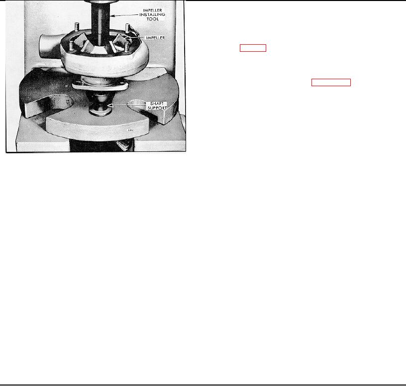
Fig. 7 - Installing Water Pump Impeller
3. Place the pump outlet flange over the pump outlet
with the flat side of the flange facing the pump body. Slip
7. If the impeller was previously pinned to the shaft
the packing ring over the pump outlet and next to the
and the old parts are reassembled, insert a .184" drill in
flange.
the pin hole in the shaft and drill a new hole in the
impeller hub. Install a new 3/16" x 7/8" groove pin.
4. Affix a new gasket to the bolting flange and place
However, if a new impeller is installed on either a new or
the pump against the blower end plate cover so that the
old shaft, it will not be necessary to pin it to the shaft
lugs on the drive coupling mesh with the lugs on the
since the impeller bore diameter has been decreased to
intermediate shaft coupling. Secure the pump to the
permit a press fit.
blower with the three bolts and seal washers.
8. Support the impeller end of the pump shaft on an
5. Slide the pump outlet packing ring and packing
arbor press and, press the coupling onto the shaft. The
flange against the cylinder block and secure the flange
drive coupling must be flush with the end of the shaft.
with two bolts and lock washers.
Make sure the drive coupling is tight on the shaft.
6. Slide the water pump inlet hose in place and secure
9. Rotate the shaft by hand to be sure the rear face of
it with the hose clamps.
the impeller blades do not rub the pump body.
7. Close the pump drain cock, and fill the engine
10. Place a new pump cover gasket against the bolting
cooling system.
flange of the pump body. Slide the pump cover over the
NOTE: When filling the cooling system of
studs and secure it to the pump body with four lock
certain models, it is necessary to open the vent
washers and nuts.
valve at the top of the thermostat housing.
Page 309

