• Home
  • Download PDF
  • Order CD-ROM
  • Order in Print
Fig. 5 - Typical Variable Speed Governor Lever Position
PREVENTIVE MAINTENANCE - TROUBLE SHOOTING

Maintenance Manual For Crane, Truck Mounted Hydraulic 25 Ton (CCE) - Vol 3 Page Navigation
  403    404    405    406    407  408  409    410    411    412    413  
img
TM 5-3810-300-24&P-3
14.14 GOVERNING DEVICE ADJUSTMENT
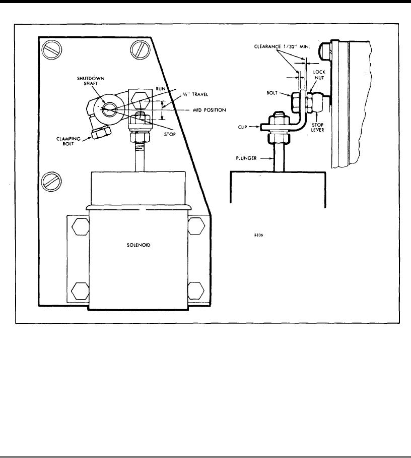
Fig. 6 - Typical Limiting Speed Governor lever Position
4
Move the lever to the stop position and observe the
NOTE: The lock nut can be either on
plunger for any possible bind. If necessary, loosen
top of or below the stop lever.
the mounting bolts and realign the solenoid to
provide free plunger motion.
Page 416


Privacy Statement
Press Release
Contact

© Copyright Integrated Publishing, Inc.. All Rights Reserved.