TM 5-3810-295-34
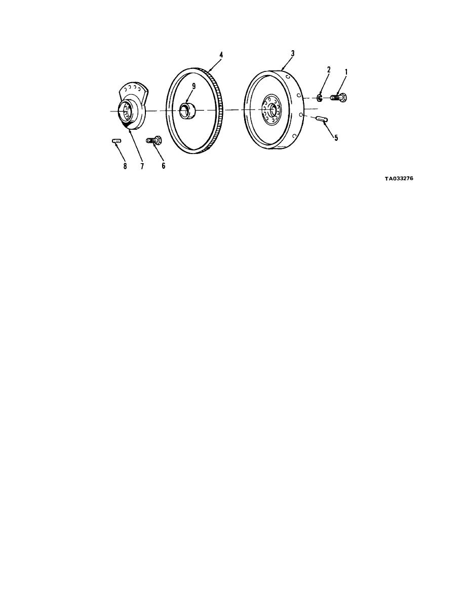
1 Screw
2 Washer
3 Flywheel
4 Gear
5 Dowel
6 Screw
7 Adapter
8 Dowel
9 Retainer Cup
Figure 14-20. Flywheel-exploded view.
flywheel.
NOTE
(4) Remove dowel (5) from flywheel.
Insert wooden block between crankshaft and
(5) Remove screws (6) and pull adapter (7)
cylinder block to prevent crankshaft from
from crankshaft using a suitable puller.
turning while removing capscrews.
(6) Remove dowel (8) and cup (9) from
(2) Remove remaining screws (1)and lock washers
adapter.
(2). Insert two puller capscrews in holes
c. Refer to figure 14-21. Remove and disassemble
provided. Turn in capscrews alternately to remove
gear housing as follows:
flywheel (3).
(1) Remove screws (1, 2, 3 and 4), lock
(3) If necessary ring gear (4) may be removed.
washers (5), and pull housing (6). Strike face of housing
Heat ring gear with a torch. Support the flywheel,
alternately on each side, with a soft hammer, to loosen.
crankshaft side down, on a solid flat surface or a hard-
(2) Remove dowels (7), preformed packing (8),
wood block that is slightly smaller than the inside
preformed packing (9) and pipe plug (14).
diameter of the ring gear. Note the chamfer on the gear
(3) Remove screws (10), lock washers (11),
teeth so that the new gear may be installed in the same
and lift cover (12) from housing. Remove gasket (13).
position. Drive ring gear (4) from the flywheel with a
suitable drift and hammer. Work around the periphery
of the flywheel to avoid binding the gear on the
14-21


