
TM 5-3810-300-24&P-3
1.4
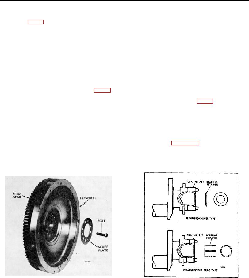
FLYWHEEL
The flywheel (Fig. 1) is attached to the rear end of the
Remove Flywheel (Transmission Removed)
crankshaft with six self-locking bolts. Two dowels in the
end of the crankshaft aid flywheel alignment and provide
1. Remove the six flywheel attaching bolts and
support when the flywheel bolts are removed. A scuff
scuff plate.
plate is used between the flywheel and the bolt heads to
prevent the bolt heads from scoring the flywheel surface.
CAUTION: If the crankshaft is not provided with dowels,
install one flywheel bolt after removing the scuff plate to
NOTE: Some early engines did not
hold the flywheel in place until the lifting tool is attached.
incorporate crankshaft dowels.
2. Attach flywheel lifting tool J 6361-01 to the
A steel ring gear, which meshes with the starting motor
flywheel with two 7/16"-14 bolts of suitable length
pinion, is shrunk onto the rim of the flywheel.
or use tool J 25026. Remove the remaining
flywheel attaching bolt.
On current engines, a split tube type retainer (Fig. 2) is
driven in the end of the crankshaft to prevent the pilot
3. Attach a chain hoist to the lifting tool to support
bearing from entering the crankshaft cavity.
the flywheel as shown in Fig. 3.
Former engines used a washer type retainer The
4. Move the upper end of the lifting tool in and out
flywheel is machined to provide true alignment with the
to loosen the flywheel, then withdraw the
clutch, and the center bore provides for installation of a
flywheel from the crankshaft and the flywheel
clutch pilot bearing. The clutch is bolted to the flywheel.
housing.
An oil seal ring, which provides an oil tight connection
5. Remove the clutch pilot bearing, if used, as
between the crankshaft and the flywheel, is fitted into a
outlined in Section 1.4.1.
groove on certain flywheel assemblies.
6. Remove the washer type pilot bearing retainer, if
The flywheel must be removed for service operations
used. It is not necessary to remove the split
such as replacing the starter ring gear, crankshaft or
tube type retainer.
flywheel housing.
Fig. 1. Typical Flywheel Assembly
Fig. 2. Pilot Bearing Retainers
PAGE 83

