
TM 5-3810-300-24-&P-3
Engine Balance 1.7
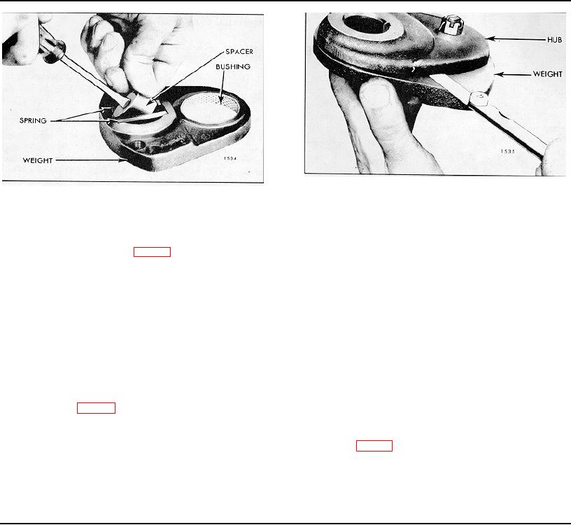
Fig. 7 - Measuring Clearance Between Balance
Fig. 6 - Installing Spring Spacer Between
Weight and Hub
Spring Packs
apply heavy cup grease to the steel faces of the washers
driver and install the spacer, tapered end first, between
and install the washers up against the camshaft and
the spring packs as shown in Fig. 6.
balance shaft end bearings.
7. Insert the journal of the hub in the bushing of the
2. Install Woodruff keys in the keyways at the front end
balance weight. The weight should swing freely on the
of the camshaft and the balance shaft.
hub. Burnish the bushing if the clearance is not within
the specified .0005 " to .0035 ".
3. Align the keyway in the balance weight hub with the
key in the shaft and slide the balance weight on the
8. Place the retainer against the spring spacer, insert
camshaft.
the bolt through the retainer, spacer and hub and secure
the bolt with a castellated nut. Tighten the nut to 25-30
4. Install the balance weight on the balance shaft in the
Ib-ft torque and lock the nut with a cotter pin.
same manner.
9. Check the clearance between the weight and the
5. Slip an internal tooth lock washer over the end of
hub as shown in Fig. 7. The specified clearance is .010"
each shaft. Start the nuts on both shafts.
to .023". Adjust the clearance by loosening or tightening
the castellated nut.
6. Place a block of wood between the balance weights
as shown in Fig. 3 and tighten the retaining nuts to 300-
Install Front Balance Weights
325 Ib-ft torque.
1. If thrust washers are used ("B" and "C" engines),
7. Install the balance weight cover, using a new gasket.
Page 112

