
TM 5-3810-300-24&P-3
OIL PUMP 4.1
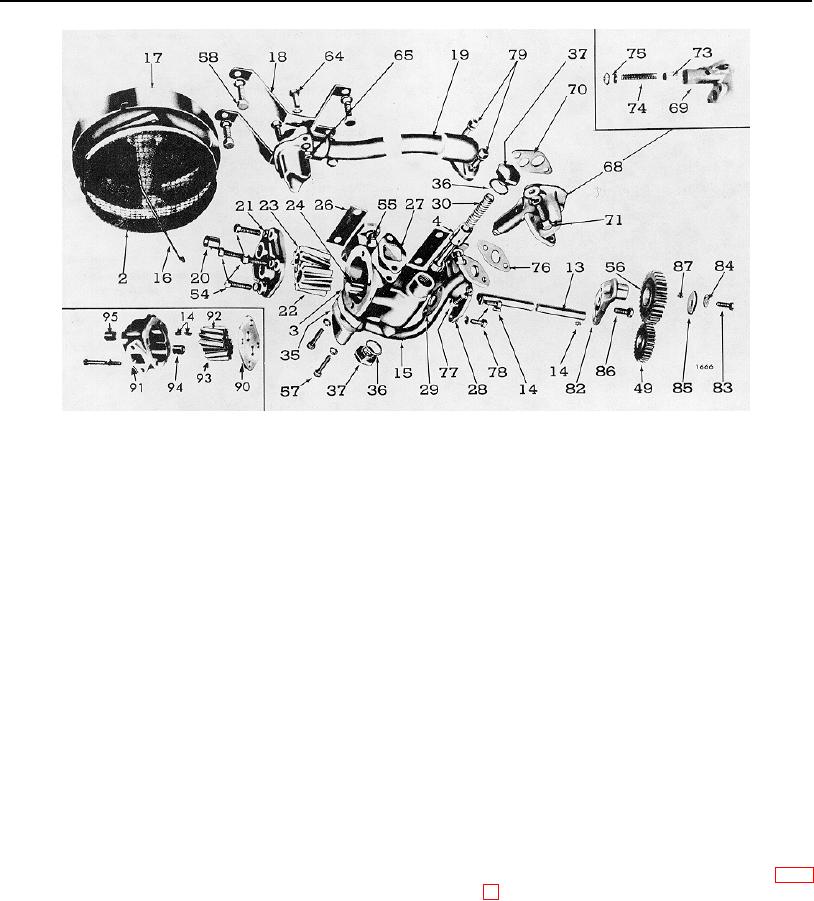
Fig. 3. Oil Pump Details and Relative Location of Parts
2.
Screen--Pump
30.
Spring--Relief
70.
Gasket--Regulator
85.
Washer--Idler
3.
Body--Oil Pump
Valve
to Cylinder Block
Gear-to-
4.
Valve--Oil
35.
Gasket--Outlet
71.
Bolt--Regulator to
Support Bolt
Pressure Relief
Pipe to Pump
Cylinder Block
86.
Bolt--Idler Gear
13.
Shaft--Drive
36.
Gasket--Copper
73.
Valve--Regulator
Support-to-
14.
Woodruff Key
37.
Plug--Relief Valve
74.
Spring--Regulator
Pump
15.
Pipe--Pump Outlet
49.
Gear--Drive-Driven
75.
Plug--Regulator
87.
Locating Pin--Idler
16.
Retainer--Screen
54.
Bolt--Pump Cover
76.
Gasket--Outlet
Gear Washer
17.
Cover--Screen
55.
Bolt--Pump to
Pipe to
88.
Dowel--Idler
18.
Bracket--Screen
Bearing Cap
Pressure Regulator
Gear Support
19.
Pipe--Pump Inlet
56.
Gear--Idler
77.
Bolt--Outlet Pipe
90.
Spacer--Pump Body
20.
Bushing--Drive
57.
Bolt--Outlet
to Pressure
91.
Body--Scavenging
Shaft (Short)
Pipe to Pump
Regulator
Pump
21.
Cover--Pump
58.
Bolt--Screen
78.
Bolt--Inlet
92.
Gear--Scavenging
22.
Gear--Driven
Bracket to
Pad Cover
Drive
23.
Gear--Drive
Bearing Cap
79.
Bolt--Inlet
93.
Gear--Scavenging
24.
Shaft--Driven Gear
64.
Bolt--Inlet Pipe
Pipe to Pump
Driven
26.
Shim
and Cover to
82.
Support--Idler Gear
94.
Bushing--Scavenging
27.
Gasket--Inlet
Bracket
83.
Bolt--Idler Gear
Driven Gear
Pipe to Pump
65.
Nut
to Support
95.
Bushing--Scavenging
28.
Cover--Pump
68.
Regulator Assy.--Oil
84.
Lock Washer--Idler
Pump Body
Inlet Pad
Pressure
Gear-to-Support
96.
Bolt--Scavenging
29.
Gasket--Pad Cover
69.
Regulator Body
Bolt
Pump Body
securing the oil pump, regulator body and oil
Remove Oil Pump
outlet tube and oil inlet tube support (including
scavenging pump tube supports if used) from
1. Remove the drain plug from the oil pan and drain
the main bearing caps, and cylinder block (Fig.
the oil.
2. Remove the oil pan bolts and remove the oil
NOTE: Remove and save the shims, if
pan.
used between the oil pump mounting
feet and the bearing caps.
3. Remove attaching bolts and lock washers
PAGE 283

