TM 10-1670-298-20&P
e.
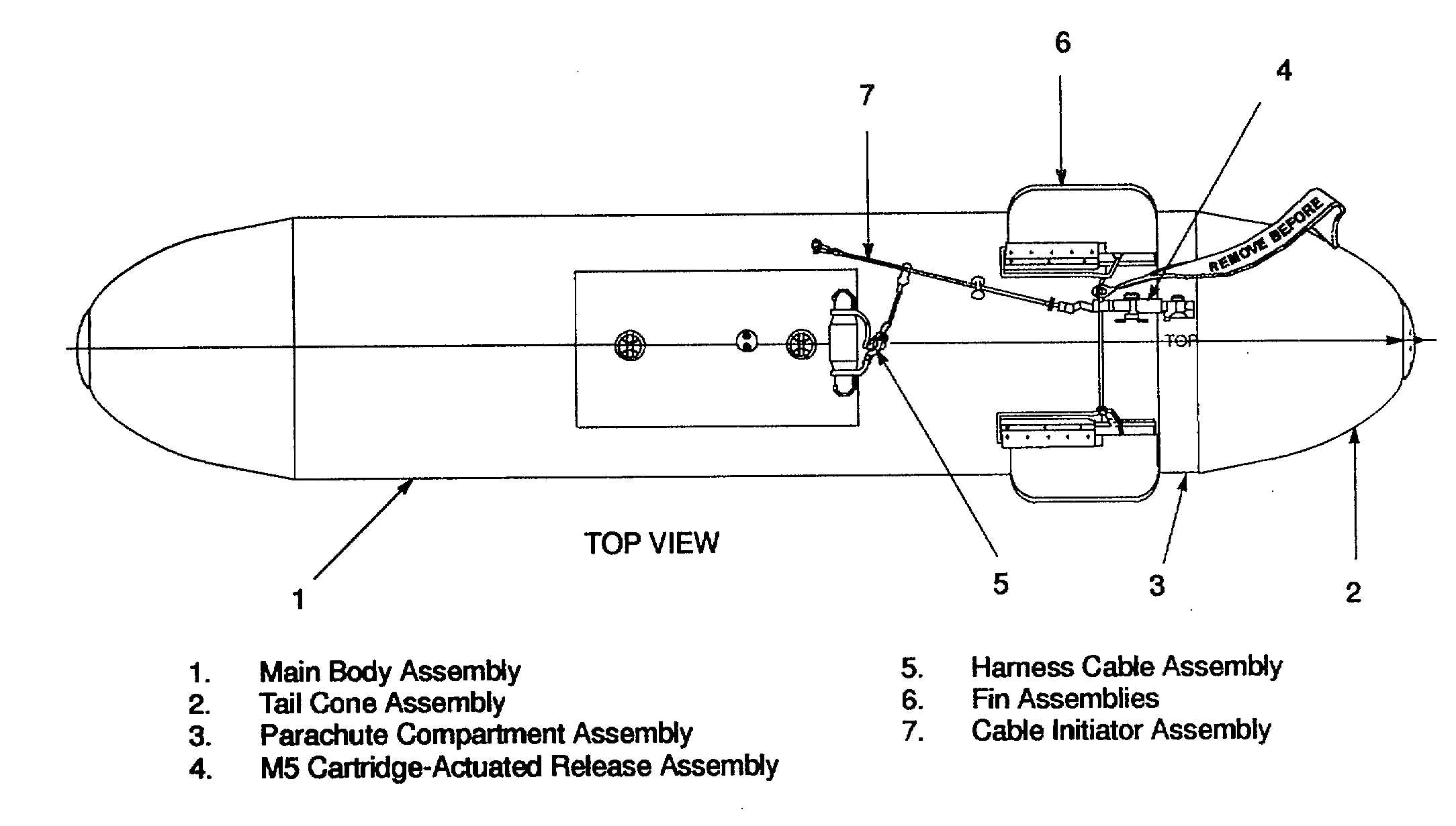
Capsule. Cargo, CTU-2/A. The CTU-2/A cargo capsule (Figure 1-10) encompasses the main body assembly (1),
the tail cone assembly (2), parachute compartment assembly (3), M5 cartridge-actuated release assembly (4),
harness cable assembly (5), fin assemblies (6), cable initiator assembly (7). Additional components not shown
are the plywood bulkhead, web assemblies, parachute cable assembly, and pin assemblies.
Figure 1-10. CTU-2/A Cargo Capsule
The container itself consists of glass filament wound acrylic resin body and associated hardware which may be disposed
of easily so it would be of no use or value to enemy forces. The cargo Is contained in the cylindrical space of the main
body between the plywood bulkhead forward and the parachute cap aft. The container, which Is fin stabilized and
structurally adequate to sustain explosive ejection from a bomb rack, is fitted with a parachute compartment and tail
cone. The M5 cartridge-actuated release assembly is a sealed device designed to exert a 250-pound (11 3.500 kg)
thrust over a 1 1/2-inch (3.810 cm) stroke following a 3/10-second delay after detonation The parachute assembly
consists of a 34-foot (10.370 m) diameter conical ringslot main parachute, a 36-inch (10 980 m) diameter guide-surface
pilot parachute, a deployment bag, and attachment bridle lines.
f. Strap Connector. 60- and 120-Inches (152 400 and 304 800 cm) Long. The 60- and 120-inch (152 400 and
304.800 cm) extraction connector straps (Figure 1-11 ) are made of 1 3/4-inch (4.445 cm) wide Type X untreated
nylon webbing with a loop at each end for attachment of the Type IV quick-fit link assembly.
1-9


