spring is compressed to a length of approximately 3 1/2
inches.
3-33. Steering Linkage, Swing Broke and Propel
Brake Adjustment
a. Steering Linkage Adjustment.
(1)Raise steering engage lever (fig. 2-24) to engage
steering gear.
(2)Turn steering wheel counterclockwise as far as it
will go. (This disengages both jaw clutches, and sets
both propel brakes in locked position).
(3)Measure distance between face of jaw clutch (1,
approximately 3/4 inch. When distance is less, turn
adjusting nut (3) and locknut (4) downward until distance
between faces measures 8s inch. When distance is
greater, turn adjusting nut (3) and locknut (4) upward
until the distance is 8/4 inch between faces.
(4)Spring tension on rod (5) against lever is
obtained by turning nuts (6) and (7) in an upward
direction.
(5)Turn steering wheel clockwise until both jaw
clutches (1) are fully engaged with recesses in brake
drum (2). When clutches are fully engaged, both propel
brakes will be in released position.
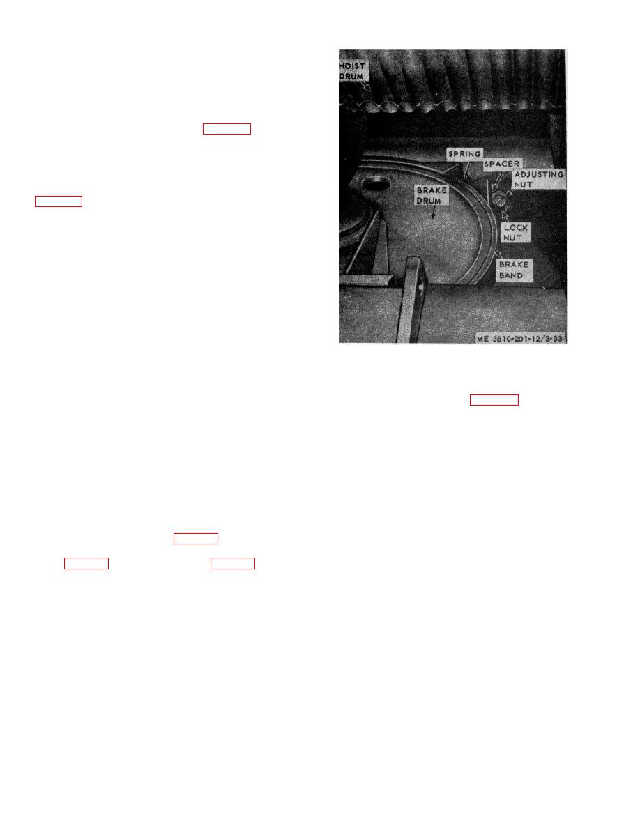
Figure 3-33. Swing brake adjustment.
(6)Back off locknut (8) and adjusting nuts (9) and
(10). Turn adjusting nut (11) on eyebolt (12) until
gear to prevent boom from lowering.
maximum tension is placed on spring (13) (the hydraulic
b. To adjust boom hoist brake, sufficient tension
cylinder must be completely compressed).
must be placed on spring (fig. 3-34) to hold boom in
(7)Pull lever (14) toward hydraulic cylinder, hold it
desired position. Position boom hoist lever in neutral.
there while tightening adjusting nuts (10) and (9) up
(With boom hoist lever in neutral brake is applied and
against linkage. The pin (15) in lever (14) must be snug
clutch is disengaged). Turn nut clockwise until brake
against top of slot in link (16).
band is tight, then tighten locknut.
b. Propel Brake Adjustment.
c. Always check clearance between thimble and side
(1)Turn steering wheel counterclockwise as far as it
plate. It should be at least 1/16 inch. Adjust this
will go. Both propel brakes will be set in locked position.
clearance, when necessary, by backing off locknut then
(2)Tighten adjusting nut (17) on bolt (18) until propel
turning adjusting screw. When clearance is correct,
brake bands are tight. Secure the adjustment with
tighten locknut.
locknut.
d. With brake applied, measure distances A and B.
c. Swing Brake Adjustment. To compensate for
Distance A should be from 8s/ inch to 1/2 inch less than
lining wear, back off locknut (fig. 3-88); tighten adjusting
distance B. Make adjustment by turning adjusting bolt
nut just enough to get the proper feel on swing brake
then tighten locknut.
lever (fig. 2-24), then tighten locknut (fig. 3-48).
Check gap between thimble and side plate after
adjusting (c. above).
3-34. Boom Hoist Brake Adjustment
a. Before making any adjustment on boom hoist
released.
brake, assure that pawl is engage in hoist drum ratchet
Note. A few drops of light engine oil on all pine
and trunnions, before adjustment, will allow
smoother operation.
3-40


