Section XIX. TRACKS
(3) Travel crane-shovel unit slowly away from
3-140. General
removed master pin until the track is flat on the ground.
This section describes maintenance procedures for the
(4) Position suitable jack under crawler frame
portion of the crawler assembly authorized at
on the side where track is being removed and raise
organization by the maintenance allocation chart. The
crawler frame until track is free of lower track roller and
track consists of track shoes pinned together around
sprocket.
drive sprockets, upper support and bottom idler rollers,
(5) Pull the track assembly from under the
to form a continuous tread for traveling for the crane-
crane-shovel unit.
shovel basic unit. Two drive chains run from sprockets
b. Cleaning, Inspection, and Repair.
on propel shaft to sprockets on track drive shaft to
(1) Clean all parts in -an approved cleaning
operate individual tracks.
solvent and dry thoroughly.
(2) Visually inspect side bars, shoulder bolts,
3-141. Track (Tread), Links, and Pins
bushings, nuts, links, link pins, master linkpins, and
a. Removal.
shoes for cracks, breaks, excessive wear, other
(1) Travel crank-shovel unit to firm ground
damage.
that is as level as possible, and stop with one of the
(3) Repair side bars by welding cracks or
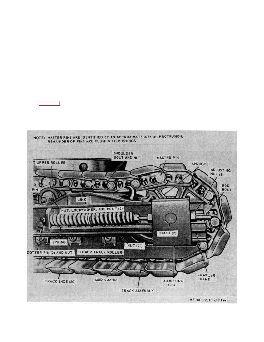
master pins (fig. 3-126) at one end of crawler frame.
breaks, and replace other components that are
(2) Drive out master pin, then remove spacer
damaged or defective.
and master bushing from link.
c. Installation.
(1) Pull the assembled track under lower
Figure 3-126. Track, removal and installation.
3-134


