1
Bolt (4 rqr)
10
Flatwasher (4 rqr)
2
Lockwasher (4 rqr)
11
Body
3
Cover
12
Plug
4
Packing
13
Front blower
5
Nut
14
Blower shaft
6
Washer
15
Seal
7
Key
16
Drain cock
8
Wire
17
Impeller
9
Capscrew (4 rqr)
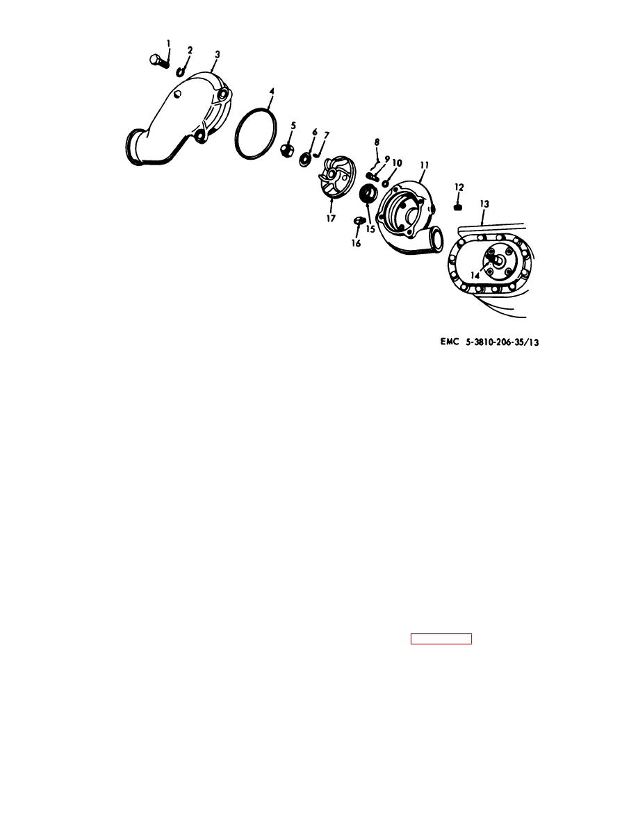
Figure 3-32. Water pump, exploded view.
(9) Install
water
pump
by
reversing
(2) Remove alternator and bracket (TM 5-
procedures in steps (1) through (8) above.
3810-201-12).
(3) Remove oil cooler oil outlet line (TM 5-
b. Cleaning, inspection, and Repair.
3810-201-12).
(4) Install a 5/16-18 NC forged eyebolt in oil
(1) Clean all corrosion from impeller and drain
cooler housing; attach a suitable lifting device; remove
cock, then clean and dry all parts thoroughly before
four mounting bolts, and remove water pump and oil
inspection or installation.
cooler as a unit.
(2) Inspect for cracks or breaks in cover or
(5) Remove four bolts securing water pump
housing, defective seal or packing, washers for bends or
housing to oil cooler.
other deformation, and mounting hardware for burs or
(6) Install by reversing procedures in steps (1)
other defect.
through (5) above.
(3) Repair by replacing defective components
b. Disassembly and Reassembly.
or mounting hardware.
(1) Refer to figure 3-33 and dissemble water pump
as required.
3-26. Water Pump for Engine Model D333TA
NOTE
a. Removal and Installation.
Impeller nut (6) is removed by turning
(1) Drain cooling system (TM 5-3810-20112).
AGO 20051A
3-41


