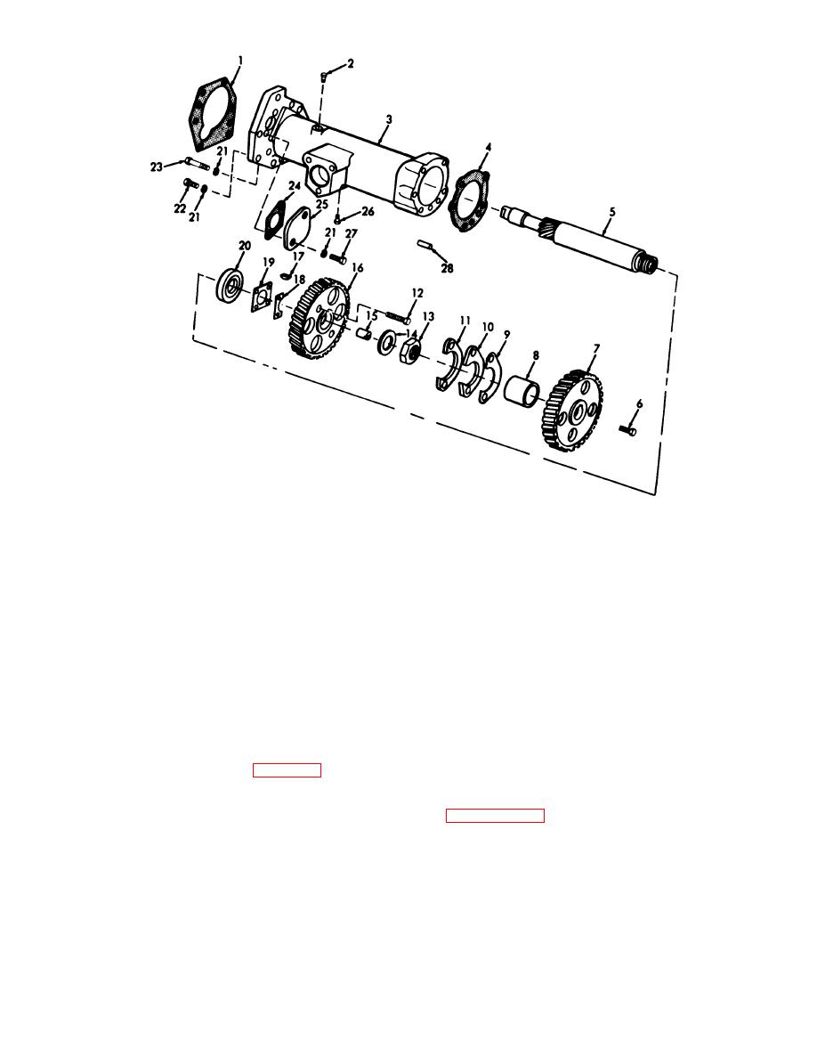
ME 3810-20135/3-41
1
Gasket
11
Spacer
21
Wear
2
Plus
12
Screw
22
Bolt
3
Housing
13
Nut
23
Bolt
4
Glut
14
Retainer
24
Gasket
5
Shaft
15
Dowel
25
Cover
6
Bolt
16
Gear
26
Plug
7
Gear
17
Key
27
Bolt
8
Bearing
18
Lock
28
Pin
9
Lock
19
Spacer plate
10
Washer
20
Bearing
Figure 3-41. Accessory drive, exploded view
(2) Remove fuel filter (TM 6581020112).
(3) Disconnect governor control linkage, then
b. Disassembly and Reassembly. Refer to figure
remove fuel injection pump housing and governor as a
3-41 and remove components as required. Reassemble
unit.
in reverse order.
(4) Remove front cover (para 3-31).
(5) Remove accessory drive gear, then
c. Cleaning, Inspection, and Repair.
Clean,
remove four bolts and locks that secure adapter housing
inspect, and repair in a manner similar to that described
to timing gear plate, and remove adapter housing.
in paragraph 3-32c above.
(6) Install by reversing procedure in steps (1)
through (5) above. Aline timing marks.
AGO 20051A
3-51


