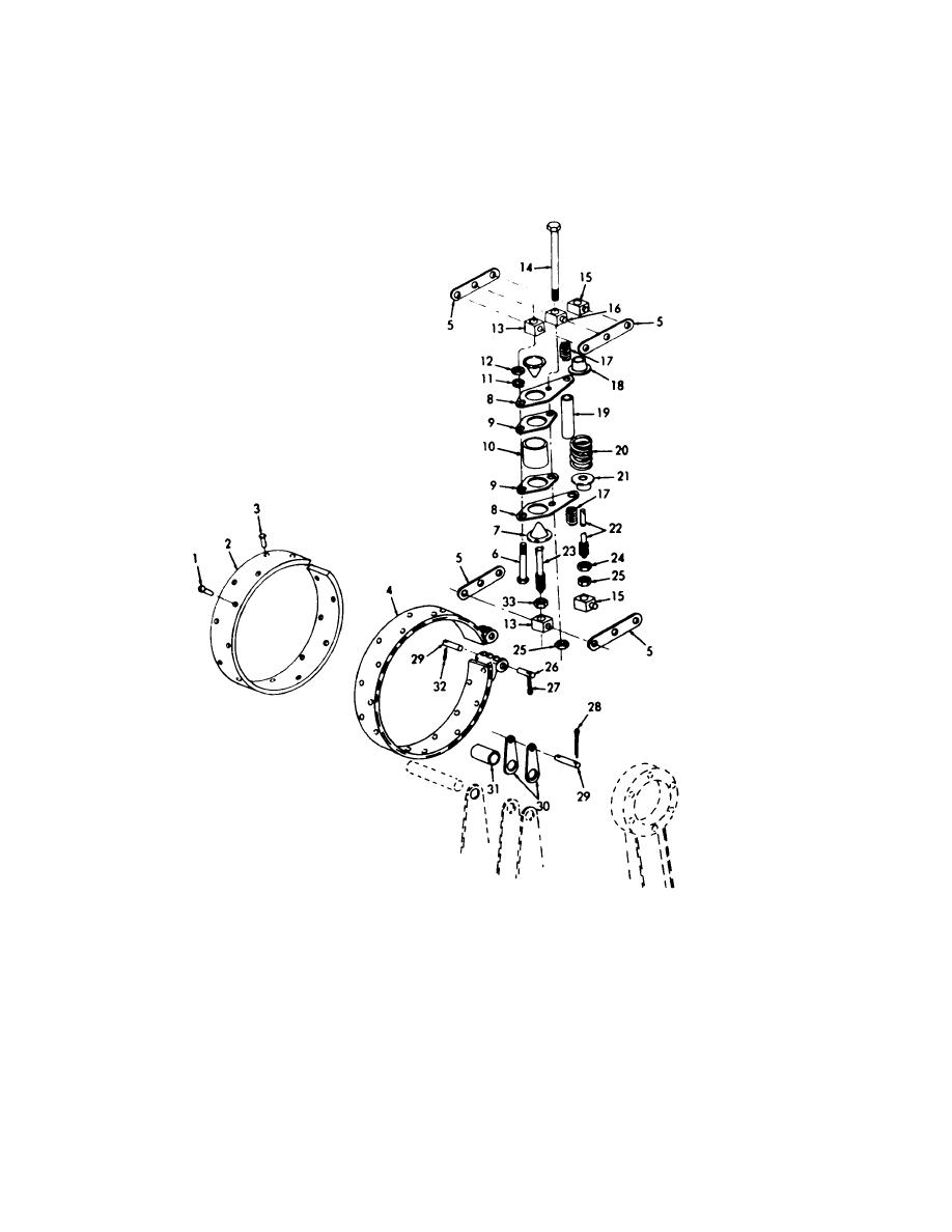
Section XIV. BOOM HOIST BRAKE
4-29.
General
4-30.
Boom Hoist Broke
a. Removal or Installation. Remove or install boom
The boom hoist brake operates on the planetary spider
on left end of the main drum (hoist) shaft. The hydraulic
hoist brake at planetary spider (TM 5-3810-201-12).
cylinder is connected to the header in lever stand.
EMC 5-3810-206-35/55
1
Rivet (10 rqr)
12
Nut (4 rqr)
23
Stud (2 rqr)
2
Lining, friction
13
Trunnion (2 rqr)
24
Nut (2 rqr
3
Rivet (31 rqr)
14
Capscrew
25
Nut (2 rqr
4
Brake band
15
Trunnion (2 rqr)
26
Pin (4 rqr)
5
Lever (4 rqr)
16
Trunnion
27
Cotterpin (4 rqr)
6
Bolts (2 rqr)
17
Spring (2 rqr)
28
Cotterpin (4 rqr)
7
Thimble (2 rqr)
18
Seat
29
Pin (2 rqr)
8
End plate (2 rqr)
19
Spacer
30
Links (4 rqr)
9
Plate (2 rqr)
20
Spring
31
Spacer
10
Cylinder hydraulic
21
Seat
32
Cotterpin (4 rqr)
11
Lockwasher (2 rqr)
22
Adjuster
33
Nut (2 rqr)
Figure 4-18. Boom hoist brake, exploded view.
AGO 20051A
4-26


