(8) Remove steering shaft mechanism (para
(14) Remove fittings (46) from bushings (47),
then remove bushings (47) when necessary.
(9) Remove four bolts (21, fig. 4-20), lock-
(15) Reassemble revolving frame by reversing
washers (22), and nuts (28), then remove cover (16) and
procedure in steps (14) through (1) above.
gaskets (15 and 23).
c. Cleaning, Inspection, and Repair.
(10) Remove six screws (18), cover (20), and
gasket (17) from bearing cover (16).
(1) Clean all parts and dry thoroughly.
(11) Remove oil seals (11 and 12) from bearing
(2) Inspect all bearings bushings, mounting
housing.
hardware, and seals for wear, damage or other defect.
(12) Remove bearings (25, 30, 31, 33, 34, 35,
Inspect revolving frame box section for dents. Inspect
36, 37, 39, and 45) from revolving frame when
sidestand for bends or dents.
necessary.
(3) Repair by welding cracks, straightening
(13) Remove dowels (26) from bearings (25
dents or bends, and replacing damaged or defective
and 37).
components or mounting hardware.
Section XVI. HYDRAULIC BRAKE AND CLUTCH CYLINDERS
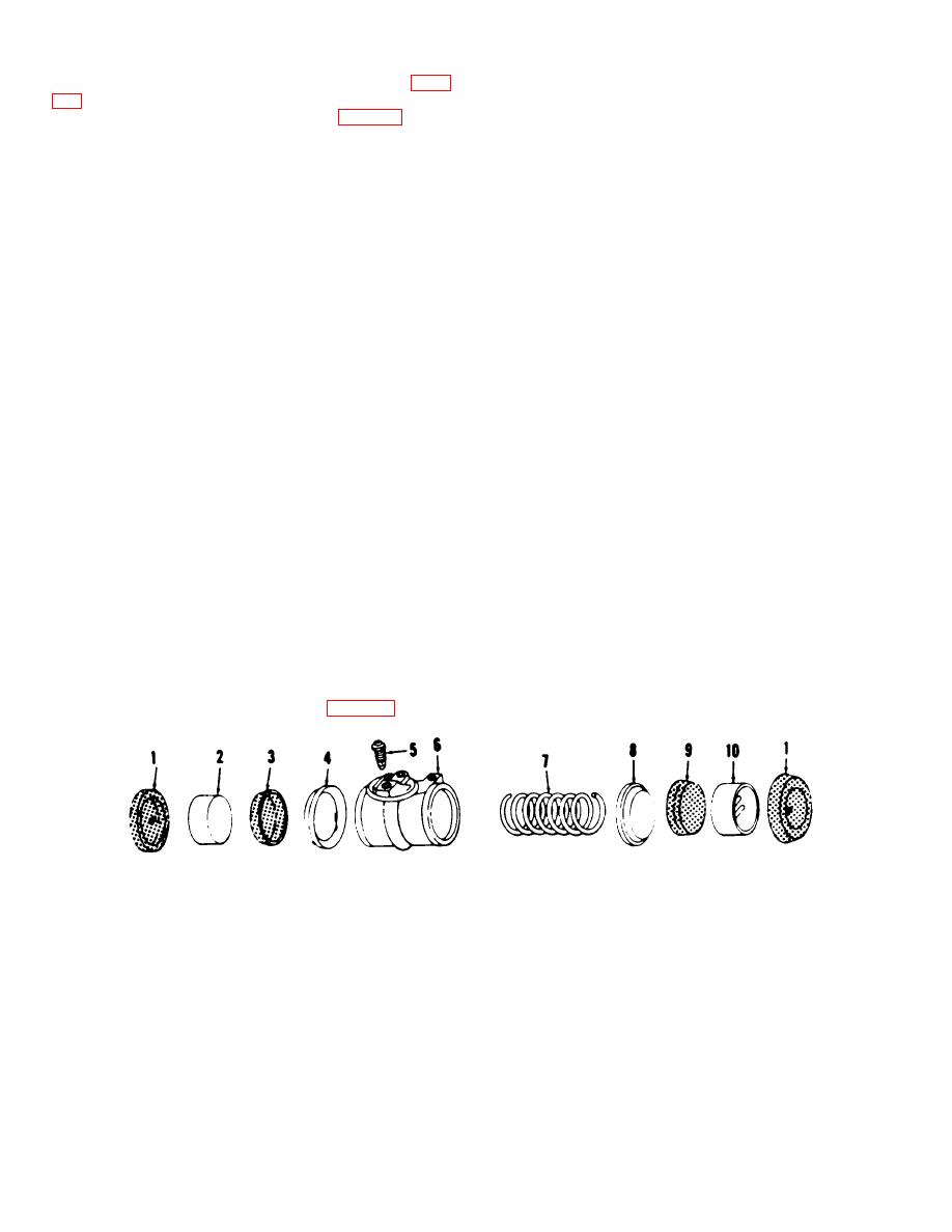
(2) Remove piston (2), cup (3) and ex-pander
4-35.
General
(4) from cylinder (6).
The operating controls receive hydraulic boost from
(3) Remove spring (7) from cylinder (6). Then
cylinders at each brake or clutch, and are equalized by
remove piston (10) cup (9), and expander (8), from
compensators at the lever stand.
Springs in the
cylinder (6).
cylinders or compensators return piston of cylinder to
(4) Remove the bleeder valve (5).
neutral position when force applies to lever or pedal has
(5) Reassemble by reversing steps (4)
been removed. This section will cover the hydraulic
through (1) above.
brake cylinder; planetary hoist, digging, and boom brake
c. Cleaning, Inspection, and Repair.
wheel cylinder; clutch and boom hoist and digging brake
compensator; jackshaft clutch and brake-drum cylinder;
(1) Clean all parts and dry thoroughly.
propel brake and planetary boom compensators, and the
(2) Inspect boots and cups for deformation or
hydraulic pressure control valve.
signs of deterioration. Inspect cylinder and pistons for
breaks, scored surfaces, or ridges of gummed fluid.
4-36.
Hydraulic Brake Cylinder
Inspect return spring for deformation and test for tension
strength. Inspect bleeder valve for damage or defect.
a. Removal and Installation. Remove or install the
(3) Repair by honing away gummed ridges or
hydraulic brake cylinder (TM 5-3810-201-12).
light scoring of pistons or cylinder. Replace defective
b. Disassembly and Reassembly.
components.
(1) Remove the two boots (1, fig. 4-21).
ME 3810-201.35/4-21
1
Boot (2 rqr)
5
Bleeder valve
9
Cup
2
Piston
6
Cylinder body
10
Piston
3
Cup
7
Spring
4
Expander
8
Expander
Figure 4-21. Hydraulic brake cylinder, exploded view.
AGO 20051A
4-30


