TM 5-3810-206-35
c. Cleaning. Read caution above, then refer to TB
(2) Reassemble in reverse order of disassembly.
ORD 651 for cleaning and flushing instructions.
c. Cleaning, Inspection, Repair, and Test. Clean,
d. Inspection, Repair and Test.
inspect, repair, and test radiator in manner described in
(1) Inspect top and bottom tanks for holes or
paragraph 3-22 above.
cracks. Repair holes or cracks by soldering or brazing.
Replace a defective tank.
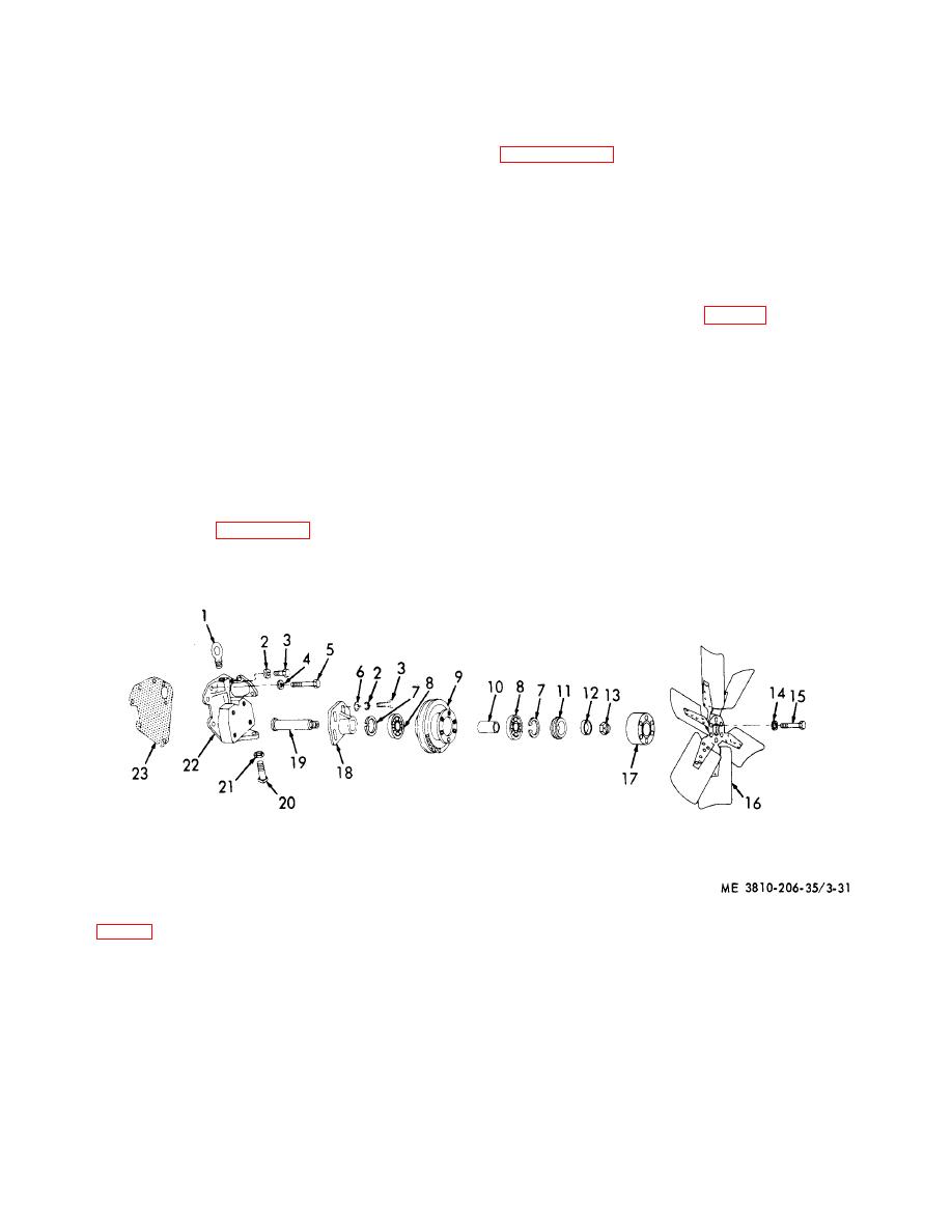
3-24. Fan for Engine Model 687C-18-ES
(2) Inspect all mounting hardware for burs,
stripped threads, or other defect. Replace defective
a. Removal and Installation. Remove or install the
mounting hardware.
fan (TM 5-3810-206-12).
(3) Inspect and test radiator core for leaks.
b. Disassembly and Reassembly.
Solder or braze all leaks, or replace the core.
(1) Remove the fan blade and fan support from
(4) Discard all gaskets.
mounting bracket (TM 5-3810-206-12).
(5) After assembly of radiator, test for leaks by
(2) Remove nut (13, fig. 3-31), washer (12), and
plugging all openings but one, where an air hose will be
pilot (11).
inserted and plugged. Immerse radiator in a tank of
(3) Remove pulley (9) and support bracket (18)
water, measure three to four psi air pressure into
from shaft (19).
radiator, then visually inspect for leaks as indicated by
(4) Remove two rings (7), two bearings (8), and
air bubbles traveling from leak to surface of the water.
spacer (10) from pulley (9).
(5) Reassemble by reversing the procedures in
steps (1) through (4) above. Install new gasket (23)
3-23. Radiator for Engine Model D333TA
when fan is installed.
a. Removal and Installation. Remove or install
c. Cleaning, Inspection, and Repair.
radiator (TM 5-3810-206-12).
(1) Clean all parts and dry thoroughly before
b. Disassembly and Reassembly.
inspection and reassembly. Discard all used gaskets.
(1) Refer to figure 3-30 and disassemble
(2) Inspect all threaded surfaces for burs or
radiator components as required.
damage. Inspect shaft for wear or straightness.
KEY to fig. 3-31:
1
Lifting eye
7
Ring (2 rqr)
13
Nut
19
Shaft
2
Lockwasher (9 rqr)
8
Bearing (2 rqr)
14
Lockwasher (6 rqr)
20
Setscrew
3
Capscrew (9 rqr)
9
Pulley
15
Capscrew (6 rqr)
21
Nut
4
Lockwasher (2 rqr)
10
Spacer
16
Fan blade
22
Fan support bracket
5
Capscrew (2 rqr)
11
Pilot
17
Spacer
23
Gasket
6
Flatwasher (4 rqr)
12
Washer
18
Adjustment support
Figure 3-31. Fan assembly, for engine model 687C-18-ES exploded view.
3-39


