TM 5-3810-207-20/TO 36C23-3-37-12
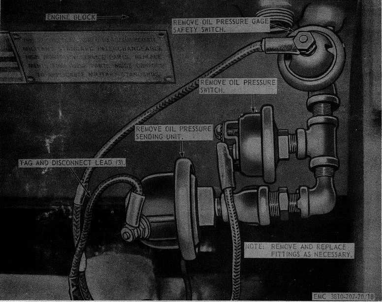
Figure 18. Oil pressure sending unit, safety switch, and oil pressure switch, removal and installation
(2) Inspect the hour-meter for breaks,
proper operation, and other damage.
Replace defective hour-meter.
c.
Installation. Install the hour-meter as
illustrated on figure 22.
85. Horn Assembly
a.
Remove the horn as instructed on figure 23.
b.
Check and replace horn button as illustrated
on figure 17.
c.
Clean and inspect. Replace defective horn
assembly.
d.
Install the horn assembly as illustrated on
figure 23.
86. Floodlights
a.
Remove the floodlight as instructed on
figure 24.
b.
Check and replace switch as illustrated on
figure 17.
c.
Disassemble the floodlight in the numerical
sequence as illustrated on figure 25.
d.
Clean and inspect all parts. Replace or
repair defective parts.
e.
Reassemble the floodlight in the reverse of
the numerical sequence as illustrated on figure 25.
f.
Install the floodlight on the crane in reverse
of the instructions on figure 24.
46