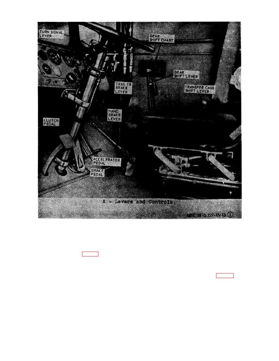
Figure 13. Carrier controls and instruments.
under the right side window defroster unit and are
the heater starts to cool. The indicator light
identical in operation.
Each control box has three
may be used as a check on the power
controls.
supply to the heater.
A spring-loaded
terminal on the light socket in connected to
(1) Indicator light (C, fig. 13). The function of
the circuit breaker so that the lamp will light
the indicator light is to show when the
when pressed in if the circuit breaker is in,
heater is in operation. It is located on the
and power is available.
left side of the control panel. The lamp
glows constantly when the heater is on
(2) Circuit breaker (C, fig. 13). The circuit
either high-fire or low-fire operation. It will
breaker is the center button of the heater
also glow when the heater has just been
control box. It is a safety device installed
shut off for approximately two minutes until
AGO 6819A
25


