TM 5-3810-288-12
broken wires, bent or broken lugs, or other damage. Repair or
replace faulty wiring as necessary.
Caution: Disconnect battery cable at battery
box (fig. 3-59) before removing control panel.
3-56.
Boom Hoist Drum Safety Pawl and
Automatic Planetary Pawl Adjustment
a. Safety Paw. Push the boom hoist drum pawl control
safety pawl (fig. 3-73) en- gage the ratchet machined into the
boom hoist drum. Pull the pawl control lever forward and
check to see that the pawl disengages from the ratchet. If the
pawl does not engage or disengage properly, refer to figure 3-73
and adjust.
b. Boom Hoist Automatic Planetary Pawls. The boom
hoist automatic planetary pawls and the friction shoes which
engage the paws are illustrated in figure 3-74. The friction
shoes automatically engage the planetary pawls when the
boom is being lowered. The pawls should not ordinarily require
adjustment. However, if the assembly has been disturbed,
refer to figure 3-74 and adjust the automatic boom hoist pawl
planetary pawls.
3-57. Shovel Front Attachment
a. General. Maintenance allocated to organizational.
level is outlined in this paragraph.
b. Shovel Boom Repair. Paint the boom a required to
prevent rust and corrosion. Refer to TM-9-213.
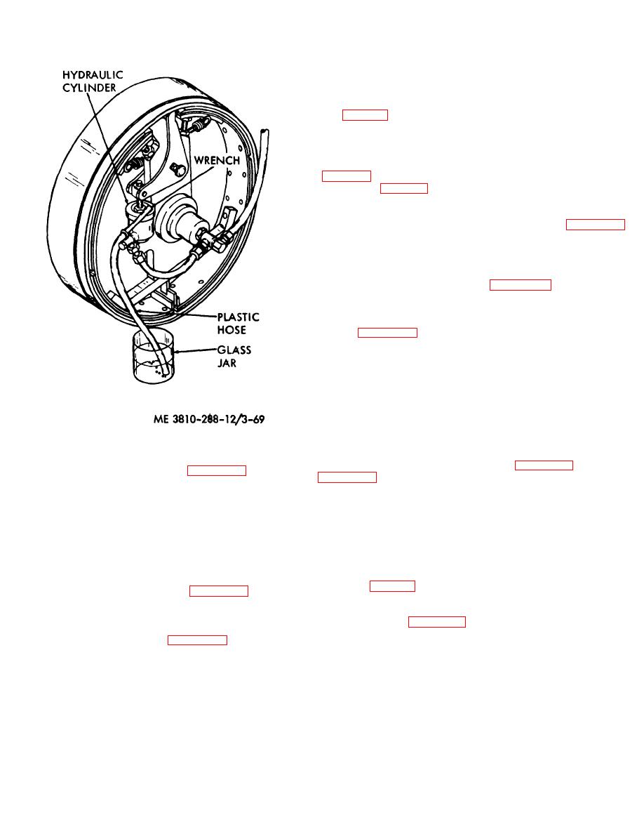
Figure 3-69. Hydraulic cylinder, bleeding procedure
c. Idle Sprocket Replacement. The idler sprocket is
bolted to the revolving frame a shown in figure 3-75. Refer to
d. Master Cylinders. Refer to figure 3-71 and remove
and replace a faulty master cylinder.
Use the same
by removing or replacing the attaching bolts.
procedure for all master cylinders.
d. Crowd Chain, Replacement and Repair.
e. Hydraulic Fluid Reservoir.
(1) Replacement. The crowd chain may be opened
(1) Service.
Service consists of keeping the
at any point for chain replacement. The easiest point will be at
hydraulic reservoir full of clean fluid of the type specified in
the boom foot drum sprocket, since the chain is accessible and
the lubrication order.
sup- ported by the sprocket. To open the chain, chisel off the
cotter pin (fig. 3-76) and drive out the chain connecting pin at
the point shown. To reinstall the chain, wrap the chain around
and replace the hydraulic fluid reservoir.
the two sprockets as shown. Make sure the chain points in the
direction shown in figure 3-76. Then support the chain on one
3-55. Control Panel
side with a heavy hammer or steel plate while installing the
a. Replacement. Refer to figure 3-72 and replace any
connecting pin and a new cotter pin.
faulty control panel mounted gauge, instrument, or switch.
b. Repair. Inspect cables for frayed insulation,
3-83


