TM 5-3810-289-12
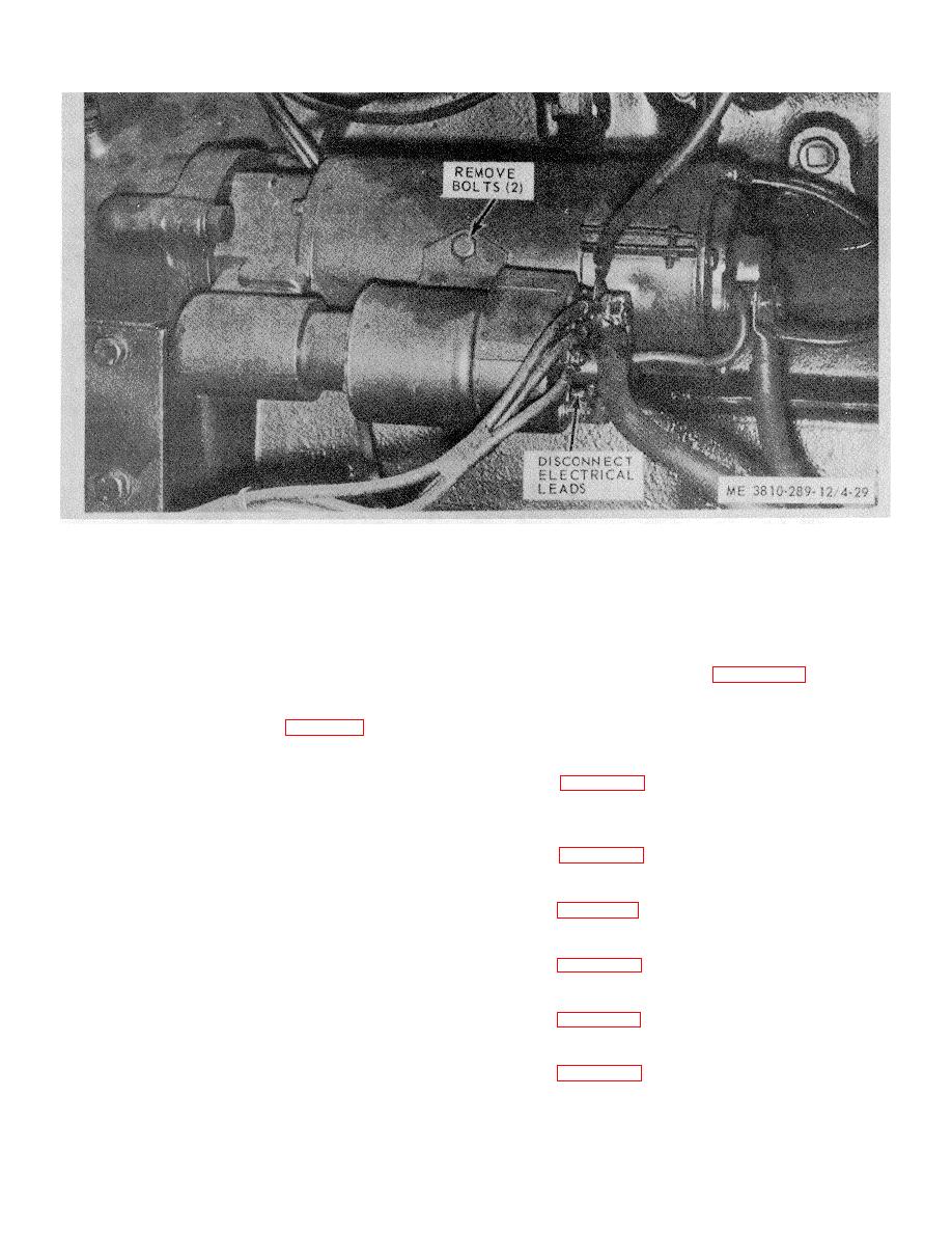
Figure 4-29. Solenoid replacement.
(3) Insert the switch shaft adjusting tool
range of 10 to 70 psi, in increments of ten, and a
through the access hole in the switch terminal housing,
temperature range of 170-210 degrees, in increments of
and turn the shaft clockwise until it bottoms. Back off
twenty. The engine safety control is not serviceable.
counterclockwise approximately five turns and push the
Failure to operate properly requires replacement of the
switch forward into the shaft housing.
Aline the
entire unit.
b. Removal. Refer to figure 4-30 and remove
mounting holes in switch with the ones in the field ring
and install two mounting screws.
the engine safety control.
c. Installation. Follow the reverse procedure
(4) Connect a 12-volt battery to the switch
terminals, numbers 1 and 4 (fig. 4-28). With the
of removal.
solenoid switch energized, gently push the drive
assembly back against the shift arm cams and check the
4-40. Switches, Gages, Meters Replacement
spacing between the face of the pinion and thrust
Refer to figure 4-31 and replace the switches, gages and
washer, using a 0.187 inch thick gage. The final-
meters on the engine control panel.
adjustment is accomplished by turning the adjusting tool
clockwise or counter clockwise until the 0.187-inch gage
4-41. Lamp Replacement
just fits between pinion and thrust washer.
Refer to figure 4-31 and replace the lamps and fuses.
Note. This adjustment must be made with the
4-42. Wiring Harness Repair
solenoid switch deenergized.
Refer to figure 4-31 and repair wiring harness.
(5) Replace the pipe plug in the switch
4-43. Floodlight and Lamp Replacement
terminal housing and seal with gasket sealer.
Refer to figure 4-31 and replace the floodlights.
4-39.
Engine Safety Control Replacement
4-44. Horn Replacement
a. General. The safety switch responds to
Refer to figure 4-31 and replace the horn.
normal temperature or pressure.
If the water
temperature goes above 210 degrees or the pressure
4-45. Panel Lights
goes below 10 psi (pounds per square inch) the safety
Refer to figure 4-30 to replace panel lights.
switch activates a warning lie on the control panel. The
safety switch can be adjusted to react within a pressure
4-39


