DETROIT DIESEL
Engine Tune-Up
SUPPLEMENTARY GOVERNING DEVICE ADJUSTMENT
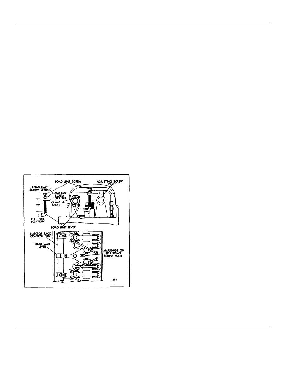
ENGINE LOAD LIMIT DEVICE
Engines with mechanical governors may be equipped
Adjustment
with a load limit device (Fig. 1) to reduce the maximum
horsepower.
After the engine tune-up is completed, make sure the
load limit device is properly installed as shown in Fig. 1.
This device consists of a load limit screw threaded into a
Make sure the counterbores in the adjusting screw plate
plate mounted between two adjacent rocker arm shaft
are up. The rocker arm shaft bracket bolts which fasten
brackets and a load limit lever clamped to the injector
the adjusting screw plate to the brackets are tightened to
control tube.
50-55 lb-ft torque. Then adjust the load limit device, on
each cylinder head, as follows:
The load limit device is located between the No. 2 and
No. 3 cylinders of a three or four cylinder engine or
1. Loosen the load limit screw lock nut and remove the
between the No. 1 and No. 2 cylinders of each cylinder
screw.
head on a V-type engine. However, when valve rocker
2. Loosen the load limit lever clamp bolts so the lever
covers with a breather are used, the load limit device is
is free to turn on the injector rack control tube.
installed between the No. I and No. 2 cylinders on in-
3. With the screw out of the plate, adjust the load limit
line engines and between the No. 2 and No. 3 cylinders
screw lock nut so the bottom of the lock nut is 7/8" from
on V-type engines to avoid interference with the rocker
the bottom of the load limit screw (Fig. 1) for the initial
cover baffles.
setting.
4. Loosen the load limit lever clamp bolts so the lever
When properly adjusted for the maximum horsepower
is free to turn on the injector rack control tube.
desired, this device limits the travel of the injector
4. Thread the load limit screw into the adjusting screw
control racks and thereby the fuel output of the injectors.
plate until the lock nut bottoms against the top of the
plate.
5. Hold the injector rack control tube in the full-fuel
position and place the load limit lever against the bottom
of the load limit screw. Then tighten the load limit lever
clamp bolts.
6. Check to ensure that the injector racks will just go
into the full-fuel position -readjust the load limit lever if
necessary.
7. Hold the load limit screw to keep it from turning,
then set the lock nut until the distance between the
bottom of the lock nut and the top of the adjusting screw
plate corresponds to the dimension (or number of turns)
stamped on the plate. Each full turn of the screw equals
.042", or .007" for each flat on the hexagon head.
NOTE: If the plate is not stamped, adjust
the load limit screw while operating the
engine on a dynamometer test stand and
note the number of turns required to
obtain the desired horsepower. Then
stamp the plate accordingly.
8. Thread the load limit screw into the plate until the
Fig. 1 Engine Load Limit Device
lock nut bottoms against the top of the plate. Be sure
the nut turns with the screw.
9. Hold the load limit screw to keep it from turning,
then tighten the lock nut to secure the setting.
Page 101


