CONTROLS AND OPERATION
SECTION II
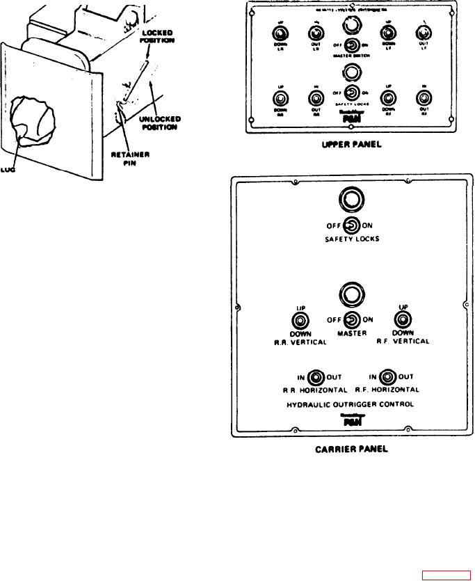
Figure 2-5. Outrigger Locks
6. Repeat Steps 4 and 6 for the outriggers on the opposite
side of the carrier. After all four outriggers have been ex-
tended and lowered, make the necessary leveling adjust-
ments by raising or lowering each outrigger as required until
the machine is Ievel. Checks the level of the machine using
the levels on each side of the carrier or in the upper cab.
7. If the machine is equipped with safety locks, engage the
safety locks by placing the SAFETY LOCKS switch in the
ON position. This step is not required if the machine is not
equipped with safety locks.
8. Return the MASTER switch to the OFF position.
NOTE
The operation of the outriggers from the upper cab is
identical to the procedure described above, except
that all four outriggers controlled from one posi-
tion in the upper cab.
Figure 2-6. Outrigger Control Panels
RETRACTING THE OUTRIGGERS. To retract the out-
riggers, proceed as follows:
3. Raise the outrigger by placing the desired VERTICAL
switch in the UP position. Repeat the procedure for the
1. Place the MASTER switch in the ON position.
other three outrigger before they are retracted.
2. Disengage the safety locks, if the machine is so e-
4. Retract each outriggar by placing the appropriate HORI-
quipped, by placing the SAFETY LOCKS switch in the
ZONTAL switch in the IN position. Be sure the lug on each
OFF position.
outrigger float engages the outrigger bum (see Figure 2-5).
NOTE
5. Remove the retainer pin, and move the lock pin to the
locked position. Install the retainer pin to maintain the lock
If the weight of the machine is resting on the safety
pin in the locked position.
locks it will be necessary to raise the machine slightly,
by placing the required VERTICAL switch in the
6. Place the MASTER switch in the OFF position.
DOWN position, to disengage the safaty locks.
2-7

