
OUTRIGGER SYSTEM
SECTION VII
SECTION VII
OUTRIGGER SYSTEM
DESCRIPTION
lic schematic, Figure 7-3, will show that the same hydraulic
pump is used to supply both the carrier power steering
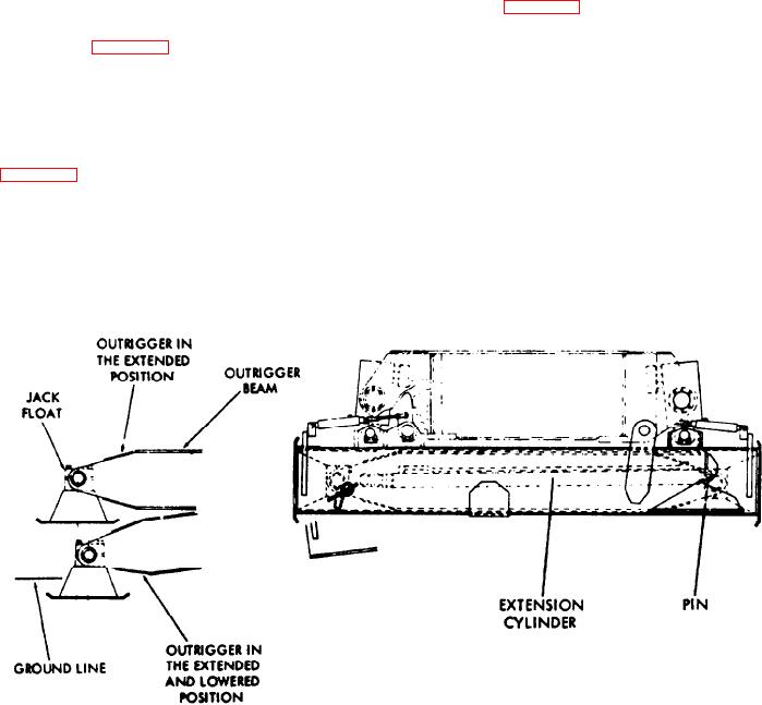
The outriggers used on this machine are hydraulically
system and the outrigger system. The pump takes supply
operated (see Figure 7-1). The outriggers are designed so
from the hydraulic reservoir and discharges through a filter
that they may be controlled from either side of the carrier,
to the steering/outrigger selector valve, located at the right
by means of electric control boxes. In addition, the control
rear of the carrier cab. With the selector valve in the out-
system can be extended to include a third control box in
rigger position, pressurized hydraulic fluid will now pass
the upper of the machine. All control boxes are wired in
through the supply line to both the front and rear solenoid
paralleI.
valve banks, and back to the hydraulic reservoir. No work
Figures 7-2 and 7-3 are diagrams of the outrigger hydraulic
will be done until one or more of the solenoid valves is
and electrical control systems. Examination of the hydrau-
actuated from one of the control boxes.
Figure 7-1. Hydraulic Outrigger Assembly
7-1