TM 5-3810-295-34
described below.
rings seat in liner. Do not force piston in liner.
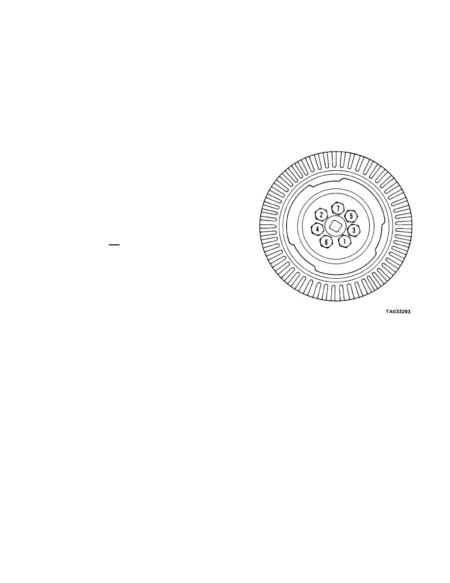
(1) Damper and crankshaft pulley shall be in
CAUTION
stalled after engine has been assembled and water
Improper use of ring compressor will cause
pump installed.
ring breakage. If band-type compressor is
(2) Position crankshaft pulley and adapter (4) to
used, make certain inner band does not slip
crankshaft aligning screw holes.
down and bind piston.
(3) Position vibration damper (3) to crankshaft
(12) Pull rod to journal with the connecting rod
pulley and align screw holes.
bolts. Coat rod bearing shell with clean engine oil and
(4) Install lock washers (2) and screws (1).
roll shell (5) into rod. Shell locking tang must fit in
Tighten in sequence shown in figure 14-37.
milled recess. Insure that oil holes in rod and shell are
properly aligned.
(13) Coat lower shell (5) with clean engine oil and
seat in cap with locking tang in place. Install rod cap
over bolts (3) so numbered side of cap is matched with
numbered side of rod.
(14) Lubricate threads of bolts (3) with clean
engine oil. Coat lockplates (2) with 140 w lubricant. In-
stall lockplates (2) and nuts (). Tighten both nuts (1) in
the following method:
(a) Tighten to 50-60 ft-lb (67.8-81.3 N- m)
(b) Tighten to 90--100 ft-lb (122.0--135.6
N. m)
(c) Loosen completely to remove all tension.
(d) Tighten to 30-40 ft-lb (40.7--4.2 N- m)
(e) Tighten to 60--70 ft-lb (81.3-94.9 N * m)
(D Tighten to 95--105 ft-lb (128.8--142.4
N. m)
(15) Bend tongs on lockplates (2) to secure nuts
(1).
(16) Repeat steps 5 through 15 to install piston
and rod assembly opposite the one completed. Secure
rod to the same crankshaft journal.
(17) Check rods for freeness and side clearance. If
Figure 14-37. Vibration damper torquing sequence.
rod is not free, loosen cap and check for dirt or burrs.
Secure cap as described in paragraph (14) above.
(18) Check for clearance between rods with feeler
(5) With a dial gauge mounted to front cover,
gauge at three locations around crankshaft. Clearance
check vibration damper eccentricity and wobble. Run-
must be 0.005-.015 inch.
out must not exceed 0.030 for both checks.
b. Refer to figure 14-33. Install vibration damper as
Section X.
CRANKSHAFT AND CYLINDER BLOCK
(4) Connect rope or hooks protected by
14-35. Removal and Disassembly
rubber hose to the crank ends. With a suitable
a. Refer to figure 14-38. Remove crankshaft as
hoist, lift crankshaft (12) from cylinder block.
follows:
NOTE
(1) Remove bearing screws (1), bearing screws (2),
Rotating crankshaft will assist in removal.
washers (3) and washers (4).
(5) Remove upper main bearing shells
(2) Using a suitable main bearing cap puller
(13) from cylinder block. Place bearing shells
loosen each main bearing. Remove bearing caps (5,6, 7,
together, marked with corresponding main
8 and 9).
bearing cap number.
NOTE
(6) If crankshaft gear (14) is damaged
Bearing shells and corresponding bearing
remove with hammer and chisel. Strike chisel
caps must be kept together in sets.
between teeth above the key-way several times to
(3) Remove lower bearing shells (10). Remove
loosen gear enough to remove by hand. Remove
thrust rings (11) from each side of rear main bearing
gear key (15).
cap and roll upper half of thrust rings (11) from block.
(7) Remove all pipe plugs (16).
14-37


