TM 5-3810-295-34
1 Cap screw
17 Wear plate
32 Screw
2 Lock washer
18 Ring
33 Wear plate
3 Preformed packing
19 Rotor
34 Ring
4 Cap screw
20 Pressure plate
35 Rotor
5 Cover
21 Vane kit
36 Pressure plate
6 Pipe plug
22 Intra vane
37 Vane kit
7 Retainer
23 Pin
38 Intra vane
8 Pipe plug
24 Bolt
39 Pin
9 Coon spring
25 Housing
40 Lock ring
10 Check valve
26 Preformed packing
41 Snap ring
11 Preformed packing
27 Valve body
42 Bearing
12 Preformed packing
28 Preformed packing
43 Shaft
13 Preformed packing
29 Preformed packing
44 Washer
14 Back-up ring
30 Back-up ring
45 Seal
15 Back-up ring
31 Back-up ring
46 Wiper
16 Screw
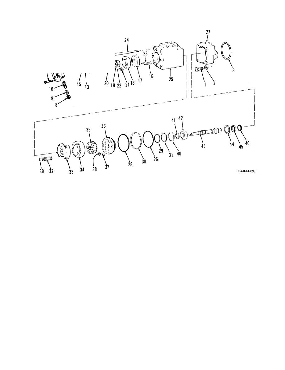
Figure 17-12. Dual steering hydraulic pump -exploded view.
(11) Remove preformed packing (28) and (29)
bearing assembly from valve body (27).
and back-up rings (30) and (31) from pressure plate (36).
(15) Remove snap ring (41) and press shaft (43)
(12) Remove screws (32) and lift wear plate (33).
out of bearing (42), supporting bearing inner race.
Remove ring (34) and rotor assembly (35) from pressure
(16) Remove washer (44) and drive shaft seal
plate (36).
(45) and wiper (46) out the shaft end of body (27).
b. Refer to figure 17-13 and remove and
NOTE
disassemble the emergency steering pump as follows:
Note position of ring (34), rotor (35), pressure
(1) Tag and disconnect all hydraulic lines to the
plate (36), vanes (21), intra vanes (22) and
pump.
locating pin (39).
(2) Remove cap screws (1) and lock washers
(13) Remove vanes (37) and intra vanes (38)
(2).
from rotor (35). Remove locating pin (39) from housing
Remove pump assembly from transmission.
(25).
(3) Mark cover (4), ring (17) and body (23). Note
(14) Remove lock ring (40) and pull shaft and
17-17


