TM 5-3810-295-34
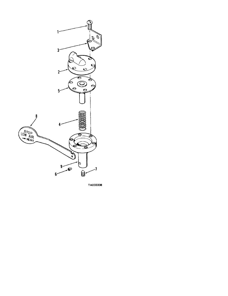
(2) Separate upper housing (2) from lower
housing (9) and remove spring (4) and diaphragm (5).
(3) Remove set screw (6) and stud (7) and
remove plate (8) from lower housing (9).
18-15. Cleaning, Inspection and Repair
a. Clean all metal parts of the pressure indicator
assembly with cleaning solvent (Fed. Spec. P-D-680 or
equivalent) and dry thoroughly.
b. Inspect all parts for cracks, breaks, excessive
wear or other damage. Repair or replace as required.
C Inspect all fittings and hardware for stripped or
damaged threads and replace as necessary.
18-16. Reassembly and Installation
a Refer to figure 18-5 and reassemble the
pressure indicator assembly as follows:
(1) Install plate (8) into lower housing and
secure with setscrew (6) and stud (7).
(2) Install spring (4) and diaphragm (5) into
lower housing and assemble lower housing (9) to
upper housing (2). Secure upper housing (2) and
lower housing (9) with screws (1).
(3) Install bracket (3) under two of the
mounting screws (1).
b. Refer to figure 18-1 and install the pressure
indicator assembly in reverse order of removal.
1 Screw
6 Setscrew
2 Upper housing
7 Stud
3 Bracket
8 Plate
4 Spring
9 Lower housing
5 Diaphragm
Figure 18-5. Air pressure indicator - exploded view.
Section VII.
REPAIR OF AIR VALVE ASSEMBLIES
treadle valve assembly as described below.
18-17. Treadle Valve Assembly
(a) Remove roll pin (1) and pin (2) from
a. Removal and Disassembly.
pedal mounting assembly.
(1) Refer to TM 5-3810-295-12 and remove the
(b) Remove cotter pin (3) and pin (4) and
treadle valve from the air brake system.
lift pedal assembly off.
(2) Refer to figure 18-6 and disassemble the
18-9


