
TM 5-3810-300-24 & P2
NOTE
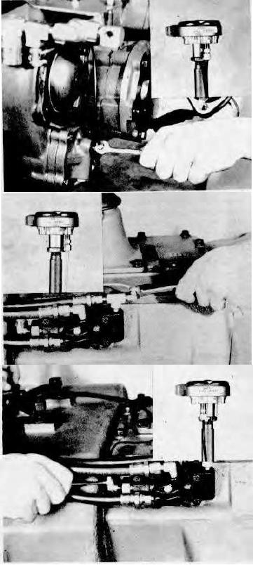
TO AVOID CONFUSION, ONLY THE AIR LINE BEING INSTALLED IN EACH OF THE FOLLOWING
THREE STEPS IS SHOWN ATTACHED TO THE CONTROL VALVE.
Connect the 1/8" OD long black air line between the
intermediate shift cylinder and the port in the control
valve identified with an "F". (See insert.)
Connect the 1/8" OD white air line between the forward
fitting on the slave air valve and the port in the control
valve identified with an "S". (See insert.)
Connect the 1/8" OD short black air line between the
rear fitting on the slave air valve and the port in the
control valve identified with an "R". (See insert.)
4-218