
TM 5-3810-300-24-&P-3
1.5 Flywheel Housing
e. If the runout exceeds the maximum limits,
remove the flywheel housing and check for dirt
or foreign material, such as old gasket material,
between the end plate, flywheel. housing and
the new gasket (and between the end plate and
the cylinder block). Also make certain the idler
gear hub and the idler gear hole spacer gaskets,
if required, are used correctly. No gaskets are
required with the hub and spacer on current
units with the roller type idler gear bearing.
f. Reinstall the flywheel housing and the flywheel
and tighten the attaching bolts in the proper
sequence and to the specified torque. Then
recheck the runout. If necessary, replace the
flywheel housing.
13.
Remove the bolts holding the lifter bracket to the
flywheel housing. Affix a new gasket to the bracket, then
alternately tighten the bracket-to-flywheel housing and
bracket-to-cylinder head bolts, thus drawing the bracket
into the corner formed by the cylinder head and housing
(Section 1.2.3).
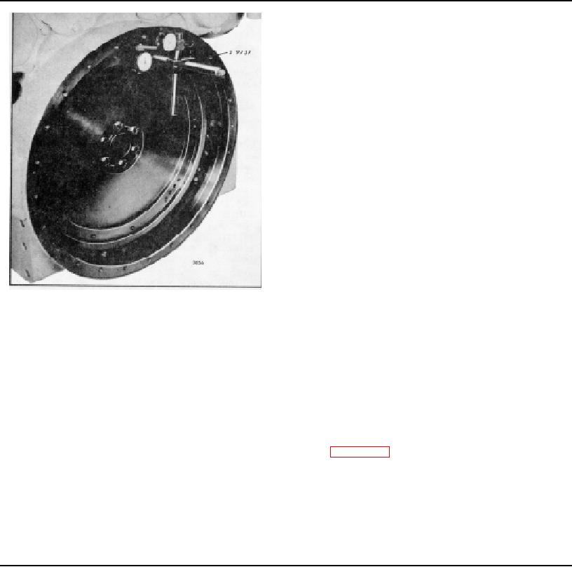
Fig. 6 - Checking Flywheel Housing Concentricity
14.
Install the oil pan.
NOTE: If the flywheel extends beyond the
15.
Remove the engine from the overhaul and
housing bell, the bore and face must be
complete assembly of the engine.
checked separately.
Use the special
adaptor in the tool set to check the housing
bore.
NOTE: The starting motor pad bolt ho, have
been relocated on certain SAE No. 1 and
c. Pry the crankshaft toward one end of the block
SAT No. 2 flywheel housings. If a current
to ensure the end play is in one direction only.
housing is installed on an early engine, the
solenoid on a Sprag clutch type starting
d. Adjust each dial indicator to read zero at the
motor may have to be repositioned. Refer to
twelve o'clock position.
Then rotate the
Section 7.3 for the indexing procedure. It
crankshaft one full revolution, taking readings at
will be necessary to replace a Dyer drive
45 intervals (8 readings each for the bore and
type starting motor with a Sprag clutch type
the bolting flange face). Stop and remove the
motor.
wrench or cranking bar before recording each
reading to ensure accuracy. The maximum total
indicator reading must not exceed .013" for
either the bore or the face.
Page 90