
TM 5-3810-300-24-&P-3
Flywheel Housing 1.5
7. Install the six "-13 housing to block bolts with lock
washers, finger tight.
8. Install the remaining flywheel housing attaching bolts
and washers, finger tight.
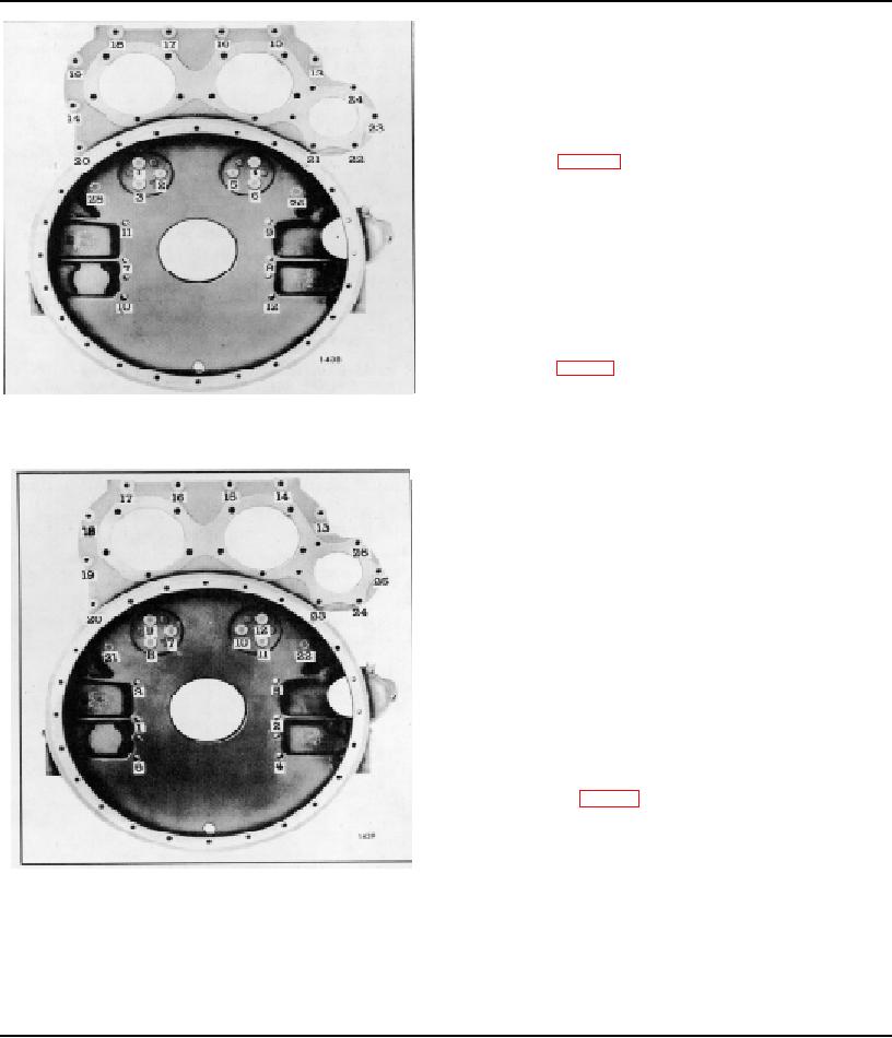
9. Refer to Fig. 4 for the bolt tightening sequence.
Start at number I and, using the proper sequence, bring
all bolts to within 10-15 lb-ft (14-22 Nm) of their specified
torque, drawing the mating parts together evenly.
NOTE: When tightening the idler gear hub
bolts, turn the crankshaft to prevent any bind
or brinelling of the idler gear bearing. The
crankshaft must be rotated for the flywheel
housing bell tightening also.
10. Refer to Fig. 5 for the final bolt tightening sequence
and, starting at number 1, tighten all of the bolts to the
specified torque. Tighten the 3/8"-16 idler gear hub and
Fig. 4 - flywheel Housing Bolt Tightening Sequence
hole spacer self-locking bolts to 40-45 lb-ft (54-61 Nm)
(Operation 1)
torque. Tighten all other 3/8"-16 and 3/8"-24 bolts to 25-
30 lb-ft (34-41 Nm) torque, and the " -13 bolts to 90-
100 lb-ft or 122-136 Nm torque (cast iron housing); or
71-75 lb-ft or 96-102 Nm torque (aluminum housing). Be
sure to rotate the crankshaft when tightening the idler
gear hub bolts and flywheel housing bell.
If drilled head idler gear hub and spacer bolts are used,
tighten them to 2540 lb-ft (34-54 Nm) torque. Line-up
the lock wire holes in the bolt heads and install the lock
wire, locking each group of three bolts together. The
wide range in the torque specification permits alignment
of the bolt heads.
11. Install the flywheel (Section 1.4).
12. Check the flywheel housing concentricity and bolting
flange face with tool set J 9737-01 as follows:
a. Refer to Fig. 6 and thread the base post J 9737-
3 tightly into one of the tapped holes in the
flywheel. Then assemble the dial indicators on
the base post.
b. Position the dial indicators straight and square
Fig. 5 - Flywheel Housing Bolt Tightening Sequence
with the flywheel housing bell face and inside
(Operation 2)
bore of the bell. Make sure each indicator has
adequate travel in each direction.
CAUTION: The self-locking bolts must be
used in sets of three. Former drilled head
bolts, if used, MUST be locked in place with
safety wire.
Page 89