
TM 5-3810-300-24&P-3
LIMITING SPEED GOVERNOR
2.7.1
e. Remove the expansion plug (41) out of the lower end
of the control housing.
f. Remove the bearing retaining screw (32), flat washer
(33), and lock washer.
g. Loosen the operating fork set screw, if used.
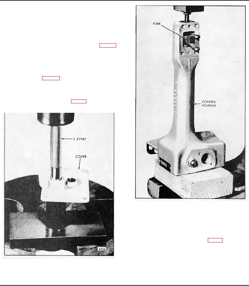
h. Support the control housing as shown in Fig. 5.
Press the operating shaft (26) from the operating fork
(73) using a brass rod. Withdraw the operating shaft,
operating lever (27), and bearing (30) as an assembly
from the control housing.
i. Support the operating shaft and lever on bed of press
as shown in Fig. 6. Press the shaft from the
operating lever and bearing with a brass rod.
3. Disassemble governor weight housing:
a. Place the weight housing (59), Fig. 9, in a soft jawed
vise. Remove the plug (83) and gasket (82).
Fig. 5 Removing Operating Fork from Operating Shaft
b. Straighten the tang of the lock washer and remove
the bearing retaining bolt (71).
c. Thread a 5/16"-24 x 3" bolt into the tapped end of the
weight shaft (66). Support the weight housing (59) on
the bed of the press as shown in Fig. 7 and press the
shaft from the bearing.
d. Slide the riser thrust bearing (60) and governor riser
(67) from the shaft (66).
Fig. 4 - Removing Needle Bearing from Governor Cover
f. This bearing is specially designed to absorb thrust
loads; therefore, looseness between the mating parts
does not indicate excessive wear.
Page 200