TM 5-3810-300-24&P-3
2.7.1.1 LIMITING SPEED GOVERNOR
Operation (Fuel Modulating Governor)
the fuel modulating gap closing speed with 80 cu. mm.
injectors, and approximately 300 rpm below fuel modulating
The fuel-modulating governor (Fig. 1) has been developed to
gap closing speed with 70 cu. mm. injectors. Delay in
improve combustion and fuel economy during low-speed full-
modulating action with 70 cu. mm. injectors is due to the helix
throttle operation. The "Fuel-Modulator" incorporated with the
design on the injector plunger, which does not reduce the fuel
mechanical limiting speed governor automatically controls the
input until after .075" rack movement.
fuel input to assure complete combustion, thus providing
maximum fuel economy, clean exhaust, and longer engine life.
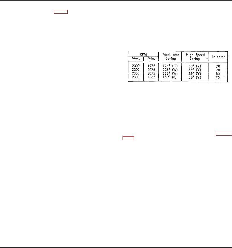
The following chart specifies proper fuel modulating and high
This control is assured regardless of the throttle setting
speed spring combination to be used at the desired full load
maintained by the operator.
engine rpm.
The governor includes a low speed spring (46), a high speed
spring (48), a set of low speed weights, and a set of high
speed weights, similar to those included in the limiting speed
mechanical governor.
In addition, the governor incorporating the "Fuel Modulator"
includes a fuel modulator spring (107), which provides
governor control for the purpose of gradually reducing the fuel
*RPM given is full load; to obtain no-load (floor setting) speed,
input in the fuel modulating range. Over this speed, the force
add 125 RPM.
of the low speed and modulator springs react against the force
of the high speed weights.
When engine is equipped with a rubber damper full load speed
must not exceed 2000 RPM. When full load speed in excess
As the engine speed decreases below top modulator range,
of 2000 RPM is desired, engine must be equipped with a fluid
the gradual reduction in high speed weight force permits the
(viscous) damper.
force of the low speed spring (46) and modulating spring (107)
Color stripe -- (W) white, (G) green, (B) brown and (Y) yellow.
to open the fuel modulator gap in the governor by moving the
low speed spring cap (47) back away from the high speed
Remove Governor
spring plunger (44). The movement of the low speed spring
cap moves the operating lever (27) -- the operating lever
moves the differential lever (23) -- toward the engine, causing
Governor operation should be checked as outlined in Section
the differential lever to rotate around the pin which connects it
2.7 before the governor is removed from the engine. If after
to the operating lever. The rotation of the differential lever is
performing these checks, the governor fails to control the
restricted by the engagement of the roller (96), on the bottom
engine properly, it should be removed and reconditioned.
of the lever, with the fuel modulator cam (101). The cam
causes the differential lever to rotate in a direction which pulls
1. Disconnect the linkage attached to the governor
the governor link back into the governor and thus pulls the
injector racks out from the full fuel position.
2. Remove the breather tube from the governor.
3. Remove four cover screws and lock washers and lift
During this time, the differential lever torsion spring (97)
the governor cover (3) and gasket (4) from the governor
opposes the above rotation with a light tension and maintains
control housing (3).
the roller (96) in its proper position against the fuel modulator
4. Disconnect the fuel rod from the differential lever
cam (101). It is this differential lever torsion spring which
(23) and the injector control tube lever.
allows the "Fuel-Modulator" to operate regardless of the
5. Disconnect the oil tube at the governor weight
throttle position maintained by the operator.
housing or cover. Remove the cover, if used.
6. Remove two governor-to-cylinder head bolt s
The fuel modulator spring tension is set so that the injector
7. Remove the control housing from the cylinder head
racks start to leave the "full in" position as the engine speed is
and the weight housing.
reduced. The engine speed at which this occurs is controlled
8. Remove the six governor weight housing-to- blower
by the rate and tension of the modulating spring used. Fuel
bolts using wrench J 4242 and withdraw the housing from the
modulating action begins at approximately 200 rpm below
blower.
Page 208

