
TM 5-3810-300-24&P-3
BLOWER 3.4
shaft until the outer face of the gear is
j. Remove the rotor timing gear installers
flush or slightly below the end of the shaft.
from the rotor shafts.
h. Start the right-hand helix gear on the shaft
Timing Blower Rotors
of the right-hand helix rotor with the gear
teeth in mesh and the omitted serrations in
After the blower rotors and timing gears are installed, the
the gear and the shaft in alignment.
blower rotors must be timed.
i. Thread an installer screw J 6270-8 in the
The blower rotors, when properly positioned in the
end of the rotor shaft until it bottoms.
housing, run with a slight clearance between the lobes.
Place the installer J 6270-6 over the screw
This clearance may be varied by moving one of the
and against the gear, and thread a nut on
helical gears in or out on the shaft relative to the other
the installer screw. Then, turn the nuts on
gear.
the installer screws uniformly clockwise
and press the gears into position tight
If the right-hand helix gear is moved out, the right-hand
against the shims and bearings as shown
helix rotor will turn counterclockwise when viewed from
in Fig. 24.
the gear end. If the left-hand helix gear is moved out,
NOTE: Both gears must be pressed on
the rotor shafts at the same time.
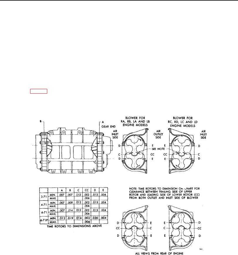
Fig.26. Chart of Minimum Clearances for Standard Blowers, Smaller Diameter Rotor Blowers and
Large Bearing (P) Blowers
PAGE 267