
TM 5-3810-300-24&P-3
BLOWER 3.4
Continue to lower the rotor until the oil seal ring
contacts the seal ring collar in the end plate;
then carefully work the oil seal ring into the
collar until the rotor contacts the end plate.
f.
Perform Steps "c" and "d" above on the left-
hand helix rotor.
g. Position the two rotors together so the lobes are
in mesh and the omitted serration in splines of
both shafts face toward the top of the end plate;
then, start the splined end of the shaft straight
into the left-hand shaft opening in the end plate.
Continue to lower the rotor in place as outlined
in Step "e".
2.
Determine the rotation of the blower being
assembled, then install the blower housing over the
rotors as follows:
a. Position the blower housing above the rotors
with its mounting flange facing toward the right-
hand helix rotor. Lower the housing over the
rotors until it contacts the dowel pins in the end
plate.
b. Align the dowel pin holes in the blower housing
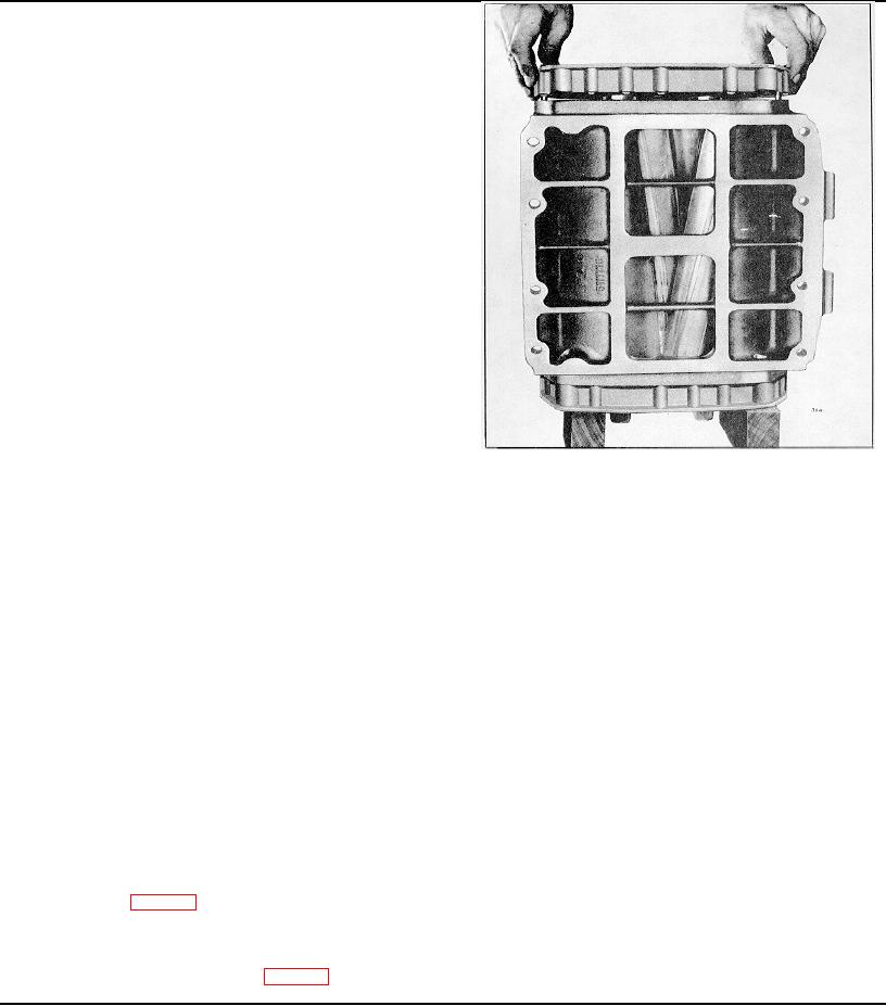
Fig. 21 - Installing Front End Plate on Blower Rotors and
with the pins and push the housing tight against
Housing (Ring Type Oil Seals)
the end plate. If necessary, tap the housing
lightly with a plastic hammer.
carefully work the dowel pins into the dowel pin
3.
Install the blower front end plate on the rotors and
holes in the housing and the oil seal rings into
housing as outlined below:
the collars. Push the end plate tight against the
housing. If necessary, tap the end plate lightly
a. Check the dowel pins. The dowel pins must
with a plastic hammer.
project .380" from the flat inner face, and .270"
from the outer face of the front end plate to
f.
Insert the two fillister head screws through the
assure proper alignment of the end plate to the
front end plate and thread them into the
housing and the cover to the end plate.
housing. Tighten the screws securely. Do not
use lock washers on these screws.
b. Lubricate the oil seal rings in the carriers on the
rotor shaft with engine oil.
Install Blower Rotor Shaft Bearings and Gears.
c.
Position the oil seal rings in the carriers so the
1.
With the blower housing, rotors and end plates still
ring protrudes from its groove the same amount
supported in a vertical position on the two wood
on each side.
blocks, install the roller bearings on the rotor shafts
and in the front end plate as follows:
d. Position the front end plate over the top of the
rotor shafts with the inner face of the end plate
a. Lubricate one of the roller bearings with engine
facing the rotors and the mark "TOP" on the
oil. Start the bearing, numbered end up, straight
end plate at the flange side of the housing as
on one of the rotor shafts.
shown in Fig. 21.
e. Lower the end plate straight over the rotor
shafts until the dowel pins in the end plate
contact the blower housing (Fig. 21); then
PAGE 263