
SUBSECTION 5C
CONTROL VALVES
2. Install a new back-up ring and O-ring on the check valve
plug with the O-ring toward the spring and ball. Place the
ball and spring in the body and install the plug. Be sure the
hole in the plug lines up with the stud hole in the body.
3. If the centering spring was removed, install the spring
and retainers on the spool. Place the O-ring in the groove
around the spool bore and install the O-ring on the spool. In-
stall the spool in the bore.
4. Install the seal rings and the seal ring retainer in the
grooves in the body of the inlet and outlet section. Carefully
place the sections together in the same order in which they
were removed. Coat the screw threads with "Locktite" or
similar sealant and install the screws and nuts. Tighten the
nuts to 15 ft-lbs torque.
5. Install the pins in each spool and assemble the levers,
fulcrum rod and "E" washers.
INSTALLATION. To install the valve, proceed as follows:
1. Position the valve on the carbody. Install the lockwash-
ers and capscrews. Fully tighten the capscrews.
2. Reconnect the hydraulic Iines.
3. Connect the flexible lines from the upper hydraulic tank
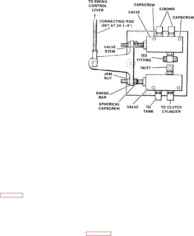
Figure 5C-5. Swing Control Valve (36Z1384)
and move the upper-lower diverting switch to the "lower"
position. Connect the battery ground cable. Start the en-
gine and operate this control to check the operation of the
valve. Check all hydraulic lines for leakage.
4. Check and adjust for an air gap between the spherical
capscrews and the valve stems. This distance must be at
SWING CONTROL VALVE (36Z1384)
least 0.010 inch or slightly more.
DESCRIPTION. Mounted below the swing control console
5. Connect the battery ground cable and start the engine.
are two pressure reducing valves that control the swing
clutch. As the swing control lever is moved forward or back,
6. Operate the swing control lever to check for proper oper-
hydraulic pressure is metered from 30 to 600 psi through
ation of the valves. Check the valve stem area and all hy-
these valves to actuate the swing clutch cylinders.
draulic lines for leaks.
The swing control valves are not repairable. If it is deter-
7. Install the sheet metal cover over the valves.
mined that the valves are defectiveor leak excessively, they
must be replaced.
BRAKE VALVE (36U259)
REMOVAL. To remove the swing control valve(s), proceed
as follows (see Figure 5C-5):
DESCRIPTION. This valve is used to apply the front and rear
drum brakes. Oil is supplied from the valve to the brake
1. Remove the sheet metal cover directly below the swing
cylinder in direct proportion to the amount of pedal pressure
console.
applied by the operator. During heavy brake applications
2. Perform the GENERAL REMOVAL procedures as found
this valve is power assisted by pressure regulating valve
in the beginning of this subsection.
(36U258).
3. Disconnect and tag the hydraulic lines to the valve.
REMOVAL. To remove the valve, proceed as follows (See
4. Remove the capscrews holding the valve in place.
5. Remove the valve to a clean, dust free area for disas-
sembly.
1. See General Removal at the beginning of this section.
INSTALLATION AND ADJUSTMENT. To install and adjust
2. Remove the top cover from over the brake valve.
the linkage to the swing control valves, proceed as follows:
3. Disconnect the hydraulic lines at the brake valve. Cap
1. Align the elbows and tees, if removed, and attach the
the lines and plug the ports of the brake valve.
valve(s) to the cabin wall with the capscrews.
4. Remove cotter pin (28), washer (19) and pin (29) from
2. Connect the hydraulic lines to the fittings.
support plates (30) and the valve stem.
5. Remove the hardware securing the valve to the bracket.
3. Check and adjust the connecting rod to a length of 24-
Remove the valve from the machine.
1/4 inches.
5C-5