
HYDRAULIC COMPONENTS
SUBSECTION 5D
NOTE
Precharge the accumulator with the precharging kit as fol-
Allow the accumulator to rest for about 30 minutes
lows (see Figure 5D-3):
and then check the precharge pressure again. Due to
the nitrogen expansion, additional precharging may
be necessary to bring the precharge to the desired
pressure.
6. The bleeder valve can be used to let out any gas pres-
sure in excess of desired precharge.
7. Retract the shaft of the air chuck by turning the bar
handle counterclockwise to the full stop position before dis-
connecting the swivel, thereby preventing excess leakage
of gas from the accumulator. Remove the chuck from the
accumulator gas valve stem.
8. The charging and gauging assembly may either be coiled
around the nitrogen cylinder or the assembly may be re-
moved from the cylinder and stored.
9. Check the accumulator gas valve assembly for leaks with
a soapy water solution or oil. If the valve core is leaking, de-
press quickly once or twice to reseat the core. It may be nec-
essary to replace the valve core if leakage continues.
10. Replace the accumulator gas valve cap and tighten
one-half turn beyond hand tightness.
11. Replace the accumulator valve guard.
12. Check for precharge loss within one week after instal-
lation.
SOLENOID VALVE (36Z1349, 36Z1528 & 36Z1423)
DESCRIPTION. Each unit is a 4-way, 2 position, spring off-
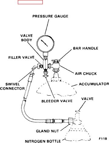
Figure 5D-3. Gauging Head lnstallation
set, solenoid operated valve. These valves are located on a
panel directly behind the operator's module and below the
upper deck panel. The valves are accessible from under-
1. Remove the valve guard and valve cap from the accu-
neath.
mulator.
NOTE
In the energized position, oil flow is from the pressure port,
through the valve and to the cylinder port to allow oper-
To read or adjust the precharge pressure, hydraulic
ation of the brake, clutch or the controls system.
fluid must be completely drained from the fluid side of
In the de-energized position (spring offset), the pressure
the accumulator.
port is blocked. Oil flow is from the cylinder port to the ex-
2. To mount the gauging head, retract the shaft in the air
haust port and then to the reservoir.
chuck by turning the bar handle counterclockwise until it
A manual plunger is provided at the end of the solenoid coil
stops. Mount the swivel of the air chuck on the accumula-
so the valve can be shifted manually in the event of an elec-
tor's gas valve stem, compressing the gasket in the swivel to
trical malfunction.
prevent gas leakage. Turn the bar handle clockwise until the
One valve mounted on a separate subplate functions the
shaft depresses the valve core in the gas valve of the
360 swing lock. This valve controls the 360 swing lock
accumulator.
cylinder.
3. Mount the gland nut of the hose assembly on the nitro-
gen bottle.
One valve mounted on a separate subplate functions the
dapper trip valve. This valve controls the dipper trip drum.
4. Remove the cap from the filler valve and attach the
The two valves, mounted on separate subplates, function as
swivel connector of the hose assembly. Hand tighten suf-
the boom hoist interlock and the boom hoist limit Valve.
ficiently to compress the gasket in the swivel connector in
These valves control the boom hoist brakes, clutch and
order to prevent gas leakage.
pawls.
5. Proceed to inflate the accumulator to 700 + 25 psi by
There are four valves mounted on one manifold which func-
opening the valve on the nitrogen bottle slowly, closing it
tion as the swing brake lock valve, propel brake valve, left
occasionally to allow the needle of the pressure gauge to
drum brake valve, and right drum brake valve. These valves
settle in position, thus giving an accurate reading of the pre-
control the swing brake, the left and right drum brake and
charge pressure. When the correct precharge has been
clutch, and the propel brakes.
reached, close the valve in the nitrogen cylinder securely.
5D-4