
SUBSECTION 11C
F U E L SYSTEM AND GOVERNOR
GENERAL
FUEL INJECTOR
This subsection contains repair -informa-
tion on the fuel injectors, variable speed
Description
mechanical governor, fuel pump and re-
lated fuel system components.
The fuel injector (Figure 11C-2 on page
11C-2 and Figure 11C-3 on page 11C-2)
is a lightweight compact unit which ena-
bles quick, easy starting directly on die-
DESCRIPTION
sel fuel and permits the use of a simple
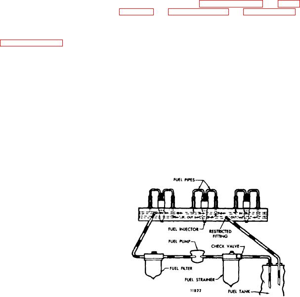
The fuel system (Figure 11C-1) includes
open type combustion chamber.
The
the fuel injectors, fuel pipes (inlet and
simplicity of design and operation pro-
outlet), fuel manifold (integral with the
vides for simplified controls and easy
cylinder head), fuel pump, fuel strainer,
adjustment.
No high pressure fuel lines
fuel filter and fuel lines.
or complicated air-fuel mixing or vaporiz-
ing devices are required.
Fuel is drawn from the supply tank
through the fuel strainer and enters the
The
fuel
injector
performs
four
fuel pump at the inlet side. Leaving the
functions:
pump under pressure, the fuel is forced
through the fuel filter and into the inlet
1. Creates the high fuel pressure re-
fuel manifold, t h e n t h r o u g h t h e f u e l
quired for efficient injection.
pipes into the inlet side of each fuel in-
jector.
2. Meters and injects the exact amount of
fuel required to handle the load.
The fuel manifolds are identified by the
words
"IN" (top passage) and OUT
(bottom passage) which are cast in se-
veral places in the side of the cylinder
head.
This aids installation of the fuel
lines.
Surplus fuel returns from the outlet side
of the injectors to the fuel return mani-
fold and then back to the supply tank.
All engines are equipped with a restric-
tive fitting in the fuel outlet manifold to
maintain the fuel system pressure. A
check valve is installed in the supply
line between the fuel tank and the fuel
strainer to prevent fuel from draining
back when the engine is shut down.
Figure 11C-1. Schematic of Fuel
System
Subsection 11C