
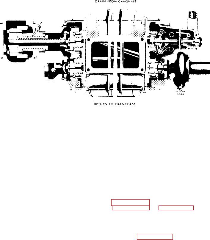
Figure 11E-2. Blower Lubrication
A slinger at the forward end of the lower
C l e a n i n g Lubrication System
rotor throws oil from the dam onto the
governor weight assembly.
Thorough flushing of the lubrication sys-
Surplus oil
overflows the dam in the two end plate
tem is required at times. Should the en-
covers and passes through drilled holes
gine
lubrication
system
become
in the cylinder block to the oil pan.
contaminated by ethylene glycol anti-
freeze solution or other soluble material,
refer to Subsection 11F for the recom-
L u b r i c a t i o n System Maintenance
mended cleaning procedure.
Use the proper viscosity grade and type
of heavy duty oil as outlined in the Lu-
OIL PUMP
brication Section III. Change the oil and
replace the oil filter elements at the peri-
o d s r e c o m m e n d e d b y t h e o i l supplier
Description
(based on his analysis of the drained en-
gine oil) to ensure trouble-free lubri-
The
gear
type
oil
pump
shown
in
cation and longer engine life.
on
page
11E-4
and
Figure 11E-4 on page 11E-5 is mounted
The oil level should never be allowed to
on the first and second main bearing
drop below the low mark on the dipstick.
caps and is gear driven from the front
Overfilling the crankcase may contribute
end of the crankshaft.
to abnormal oil consumption, high oil
temperature, and also result in oil leak-
The oil pump helical gears rotate inside a
ing past the crankshaft rear oil seal.
housing
on
page
11E-4).
The drive gear (23) is keyed to the
To obtain the true oil level, the engine
drive shaft which is supported inside the
should be stopped and sufficient time
housing on two bushings with a
(approximately twenty minutes) allowed
drive-driven gear keyed to the outer end
for the oil to drain back from the various
of the shaft.
The driven gear (24) is
parts of the engine.
If more oil is re-
supported on t h e d r i v e n g e a r s h a f t
quired, add only enough to bring the
which is pressed into the pump body.
level to the full mark on the dipstick.
An integral plunger-type relief valve (4)
by-passes excess oil to the inlet side of
the pump when the pressure in the oil
L u b r i c a t i o n System