TM 5-3810-307-24-1-1
6.
Install the air lines to the brakes as tagged
WARNING
during removal.
Do not allow the axle to twist or tilt when
7.
If applicable, install the hydraulic lines to the
removing the mounting hardware.
steer cylinders as tagged during removal. Bleed the
steering system if necessary.
NOTE
8.
Install the tire and wheel assemblies, refer to
MOUNTING WHEEL ASSEMBLIES.
Each
axle
assembly
weighs
approximately 1600 pounds (726 kg).
9.
Build up pressure in the air system.
10. Refer to LUBRICATION CHART (Chapter 1,
9.
With an adequate lifting/supporting device
Section 4) and service the axle.
supporting the weight of the axle, remove the nuts,
washers, bolts, and cotter pins securing the
11.
Remove the blocking.
oscillation lockout cylinder lower retaining pins and
remove the retaining pins.
12.
Retract and stow the outriggers.
10. Remove the bolts and washers securing the
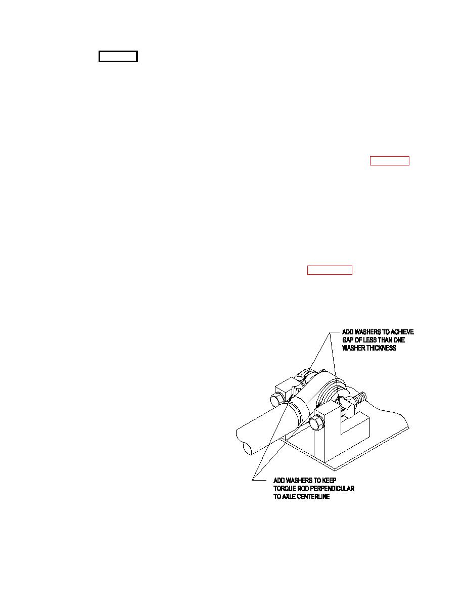
13. With full weight of crane on tires, boom in
axle to the leaf springs.
boom rest, and oscillation cylinders unlocked, check
gap between torque rod and axle mount. Gap must
11. Remove the axle and move it to a clean work
be less than one washer thickness. Ensure torque
area.
rod is perpendicular to the axle center line. Add
washers as shown in Figure 2-4-1 to achieve stated
INSTALLATION.
conditions. Torque nuts securing torque rod to axle
mount 567 to 615 pounds-foot (769 to 834 Nm).
1.
Using an adequate lifting/supporting device,
position the axle under the crane.
2.
Apply Loctite #271 to the bolt threads and
install the bolts and washers securing the axle to the
leaf springs.
3.
Install the oscillation lockout cylinder lower
retaining pins and secure in place with the cotter
pins, bolts, washers, and nuts. Torque the bolts to
75 pounds- foot (102 Nm).
NOTE
Step 4 applies only to the front axle.
4.
Secure the drag link to the steering arm with
the hex nut and cotter pin. Torque the nut to 215
pounds-foot (291 Nm) then back the nut off to the
nearest cotter pin hole and install the cotter pin.
Secure the torque rod to the axle assembly with
capscrews, washers (as marked during removal),
and hex nuts. Do not torque nuts at this time.
5.
Install the drive lines. Refer to DRIVE LINES
in Section 3 - DRIVE TRAIN.
2-4-6


