TM 5-3810-307-24-1-2
6. LENGTH READING PROBLEM - continued
PREVIOUS PAGE
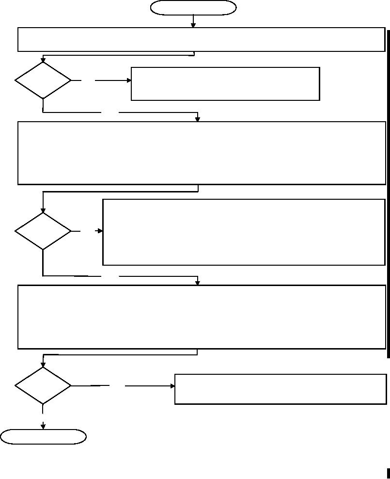
Measure power supply to length potentiometer in cable reel between terminal 1 (ground) and
3 (-5v) on terminal board. Refer to Drawing 2, 4, 17 in Section 10.
Correct?
NO
Faulty wiring between central unit and
length potentiometer. Check wiring.
YES
Measure signal from length potentiometer in cable reel between terminal 2 (signal) and 1 (ground)
on terminal board. The measurement should be between 0.5 volts and 4.5 volts. 0.5 volts with
the boom fully retracted and the length potentiometer set fully counterclockwise to a soft stop
(minimum sensor output). 2.1 volts (0.1 V) with boom fully extended (actual working range).
4.5 volts with the potentiometer turned completely clockwise 10 turns to a soft stop (maximum
sensor output). Refer to Drawing 2, 4, 17 in Section 10.
Replace length potentiometer assembly. Remove slip ring body from shaft
and remove gear wheel from potentiometer axle. Unscrew mounting plate and
remove potentiometer assembly from mounting plate. Remove assembly
Correct?
NO wires from terminal block. Connect new assembly to terminal block. Reinstall
mounting plate, gear wheel and slip ring. With boom fully retracted, reset
potentiometer by turning counter-clockwise until it reaches a soft stop.
Refer to Drawing 2, 4 in Section 10 and Procedure 5 in Section 11.
YES
Measure signal from length potentiometer in central unit connection board between X1-8 (ground)
and X1-10. The measurement should be between 0.5 volts and 4.5 volts. 0.5 volts with the
boom fully retracted and the length potentiometer set fully counterclockwise to a soft stop (minimum
sensor output). 2.1 volts (0.1 V) with boom fully extended (actual working range). 4.5 volts with
the potentiometer turned completely clockwise 10 turns to a soft stop (maximum sensor output).
Refer to Drawing 2, 3, 18 in Section 10.
Correct?
NO
Faulty wiring between central unit and cable reel.
Check wiring
YES
NEXT PAGE
Change-1 G-19

