
TM 5-3810-307-24-2-2
Component or Assembly (Procedure)
Ref. No./Steps
Metric
U.S.
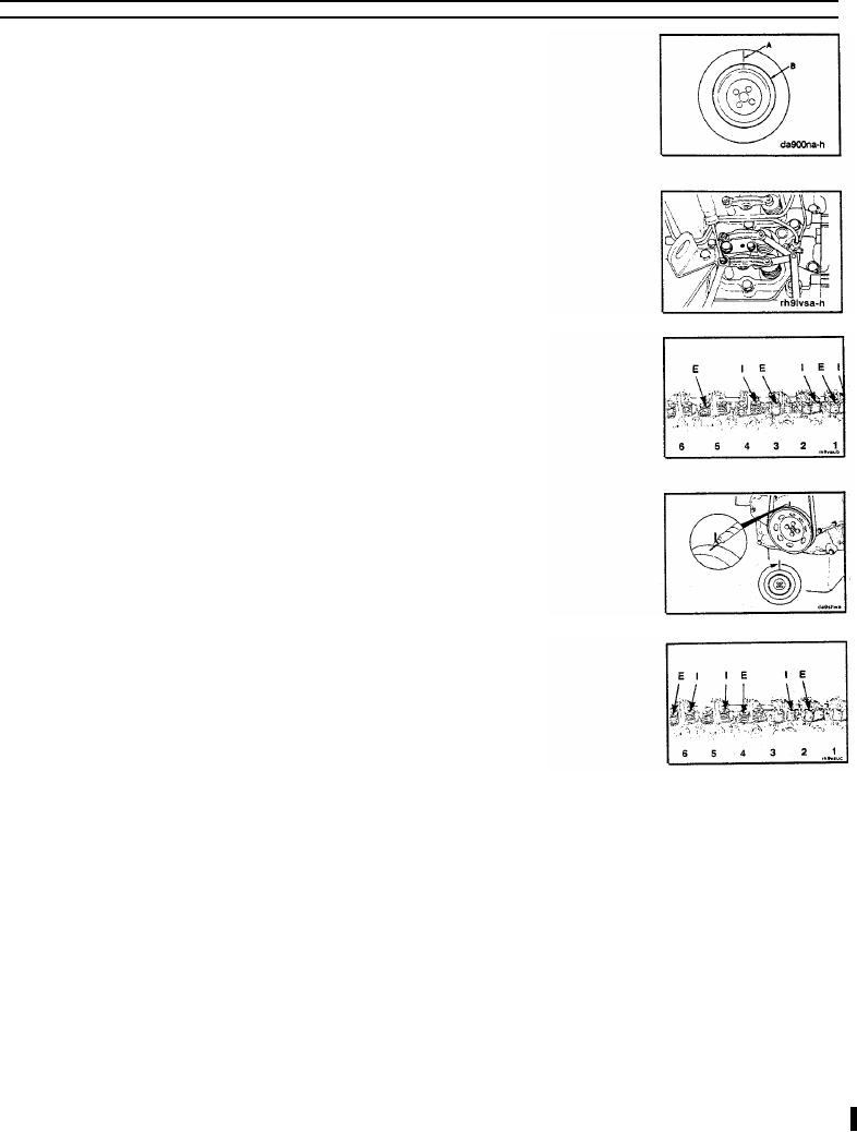
Vibration Damper
Index line out of alignment
A
1.588 mm
MAX
0.0625 in
Missing rubber member chunks
B
3.175 mm
MAX
0.1250 in
Valve Stem to Rocker Lever Clearances
Intake
0.25 mm
0.010 in
0.51 mm
0.020 in
Locknut
34 Nm
25 ft-lb
Valve Adjustment Procedure
Perform Step A of the valve set procedure with cylinder No. 1 at TDC compression stroke (timing
pin will engage).
Step A - Six Cylinder
Perform Step B of the valve set procedure with cylinder No. 1 at TDC plus 360 degrees (timing pin
will not engage).
Mark the crankshaft and gear cover. Rotate the crankshaft one full turn in the direction of engine
rotation.
Step B Six Cylinder
V-9 C-1