
TM 5-3810-300-24&P-3
1.2.2 EXHAUST VALVES
8. Remove the valve bridge and reinstall it in its
2. Install the valve bridge on the valve bridge guide,
ORIGINAL position with the spring in place (if a
without the spring (if a spring-loaded bridge is
spring-loaded bridge is used).
used).
9. Adjust the remaining valve bridges in the same
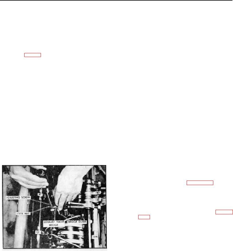
3. While firmly pressing straight down on the pallet
manner.
surface of the valve bridge, turn the adjusting
screw clockwise until it just touches the valve
10. Swing the rocker arm assembly into position,
stem. Then, turn the screw an additional 1/8 to
making sure the valve bridges are properly
1/4 turn clockwise and tighten the lock nut finger
positioned on the rear valve stems.
This
tight (Fig. 21).
precaution is necessary to prevent valve damage
due to mislocated valve bridges. Tighten the
4. Remove the valve bridge and place it in a vise.
rocker arm shaft bracket bolts to the torque
Use a screw driver to hold the adjustment screw
specified in Section 1.2.0.
from turning and tighten the lock nut to 20-25 lb-
ft torque.
11. Align the fuel pipes and connect them to the
injectors and the fuel connectors. Use socket J
5. Lubricate the valve bridge guide and the valve
8932-01 and a torque wrench to tighten the
bridge with engine oil.
connections to 12-15 lb-ft torque.
6. Reinstall the valve bridge in its ORIGINAL
position, without the spring (if a spring-loaded
CAUTION: Do not bend the fuel pipes
bridge is used).
and do not exceed the specified torque.
Excessive tightening will twist or fracture
7. Place a .0015" feeler gage J 23185 under each
the flared ends of the fuel pipes and
end of the valve bridge. Use a narrow strip cut
result in leaks. Lubricating oil diluted by
from .0015" feeler stock to fit in the bridge
fuel oil can cause serious damage to the
locating groove over the inner exhaust valve.
engine bearings.
While pressing down on the pallet surface of the
valve bridge, both feeler gages must be tight. If
12. Fill the cooling system.
both of the feeler gages are not tight, readjust
the adjusting screw as outlined in Steps 3 and 4.
NOTE: Remove the vent plug from the
thermostat housing or open the vent
valve when filling the cooling system.
13. Adjust the exhaust valve clearance and time the
injectors as outlined in Section 14.1 and 14.2
before starting the engine.
14. Start the engine and check for leaks in the fuel,
water and lubrication systems.
15. Perform the final tune-up as outlined in Section
14 after the engine has reached its normal
operating temperature.
16. Install the valve rocker cover.
Fig. 21. Valve Bridge Adjustment
PAGE 59

