
TM 5-3810-300-24-&P-3
1.6.3
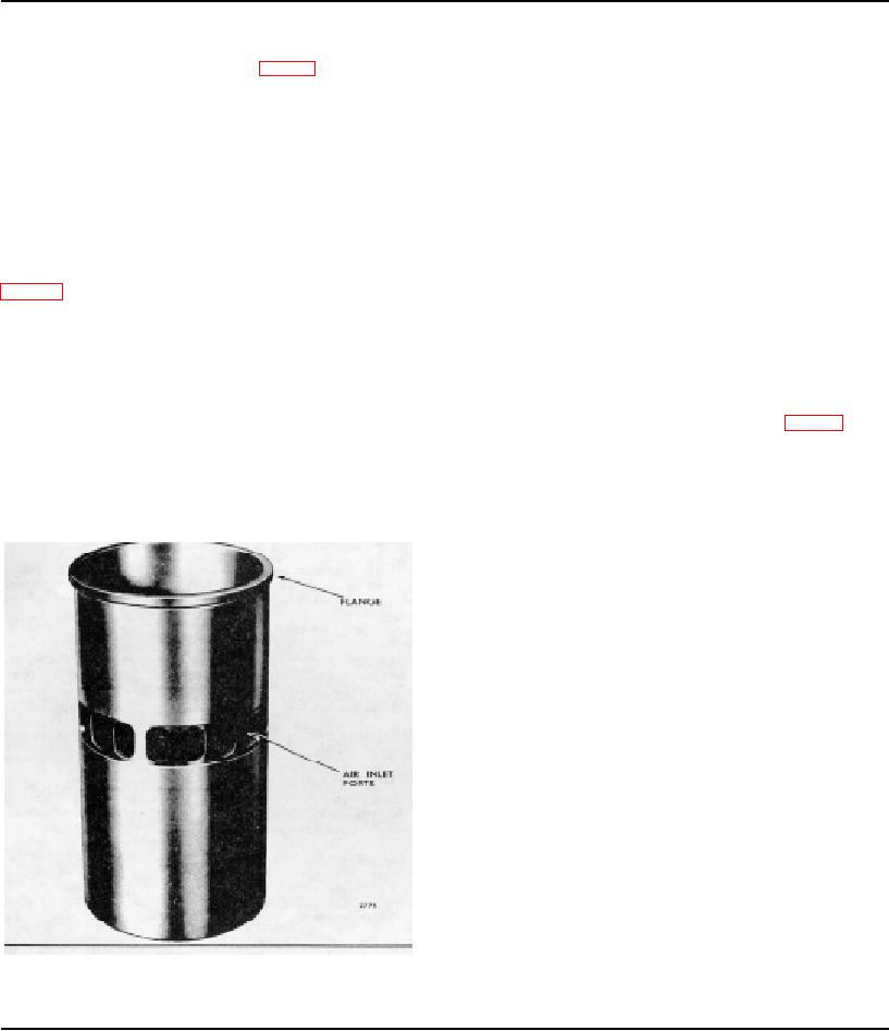
CYLINDER LINER
The replaceable type cylinder liner (Fig. 1) is accurately
according to the surroundings in which the engine is
machined and heat treated to provide a long wearing
operating.
scuff-resistant surface. The flange at the top fits into a
counterbore in the cylinder block and rests on a
Inspect Air Inlet Ports
replaceable cast iron insert which permits accurate
alignment of the cylinder liner. Compression is sealed
The air inlet ports in the cylinder liner should be kept free
with an individual laminated compression gasket for each
of carbon formation for efficient engine operation. To
cylinder.
avoid sludge accumulation at the ports, use the proper
types of fuel and lubricating oil as specified and change
The liner is cooled by means of a water jacket in the
the lubricating oil and oil filters at regular intervals.
cylinder block and by the scavenging air introduced into
Maintain the engine at its specified operating
the cylinder through the air inlet ports around the liner
temperature and avoid prolonged periods at idle speed
(Figs. 1 and 2). The air inlet ports are machined at an
or light loads. When idling is necessary, maintain the
angle to create a uniform swirling motion to the air as it
engine speed at about 800 rpm. Also keep the injectors
enters the cylinder. This motion persists throughout the
timed correctly. If necessary, clean the air inlet ports,
compression stroke and facilitates scavenging and
without removing the liners, as follows:
1. Remove the cylinder head and air box covers.
The wear on a liner and piston is directly related to the
amount of abrasive dust and dirt introduced into the
2. Install a cylinder liner hold-down clamp (Fig. 3).
engine combustion chamber through the air intake. This
dust, combined with lubricating oil on the cylinder wall,
3. Hand crank the engine until the piston, in the liner
forms a lapping compound and will result in rapid wear.
whose ports are to be cleaned, is at the bottom of its
Therefore, to avoid pulling contaminated air into the
stroke.
cylinder, the air cleaners must be serviced regularly
4. Clean all of the ports, with a suitable tool or pointed
hardwood stick, from the inside of each liner. Then
remove all chunks of carbon from the air box and make
sure the air box drains are open.
5. After cleaning the ports, examine the inside of the
liner around the ports for burrs. Remove burrs by hand
with 250 grit emery paper. Failure to remove burrs can
result in early failure of the pistons and rings.
6. Remove the hold-down clamp.
7. Install the cylinder head and air box covers.
The air inlet ports may also be cleaned by removing the
liners and placing them in a hot caustic soda or lye
solution long enough to loosen the carbon deposits.
Final cleaning may then be accomplished by brushing
the loosened carbon deposits from the ports.
Remove Cylinder Liner (Cast Iron Cylinder Block)
It is very important that the proper method is followed
when removing a cylinder liner. Do not attempt to push
Fig. 1 - Typical Cylinder Liner
the liner out by inserting a bar in the liner ports
Page 102

