
SUBSECTION 5D
HYDRAULIC COMPONENTS
REMOVAL. The removal of any of these valves does not re-
There are also two valves mounted on one manifold which
quire the disconnection of hydraulic lines. Each valve is
function as left and right drum pawl valves. These valves
held to a subplate or a manifold by four socket head screws.
control the left and right drum pawls.
To remove a valve, proceed as follows (see Figure 5D-4):
TROUBLESHOOTING. The table and maintenance hints
that follow are of a general nature, but should provide help-
ful information when combined with the schematic in Sub-
section 5A.
Before breaking any circuit, be sure all pawl
locks are engaged and block or lower any load
Table 5D-1 lists the common difficulties experienced with
whose movement could generate pressure.
directional valves and systems. It also indicates the
probable causes and remedies for each of the troubles
1. Complete the General Removal instructions at the
listed.
beginning of this subsection.
It should always be remembered that many apparent valve
2. Remove plate (01), move gasket (02) aside and discon-
failures are actually the failure of other parts of the system.
nect the solenoid wiring. Mark or tag the wires to ensure
The cause of improper operation is best diagnosed with
proper assembly. Set aside terminal block (32) and plate and
adequate testing equipment and a thorough understand-
gaskets (33) until installation.
ing of the complete hydraulic system.
3. Remove the four socket head screws from the wiring
SOLENOID REPLACEMENT. It is not necessary to remove
cavity inside the valve body. The valve can now be removed
the valve to replace the solenoid coil. After determining the
from the machine. Be ready to catch the oil that is retained
solenoid coil is defective, proceed as follows (see Figure 5D-
in the lines and the valve.
4):
4. Cap all the system openings to prevent the entrance of
DISASSEMBLY. To disassemble the valve, proceed as fol-
Before breaking an electrical circuit, be sure
lows (see Figure 5D-4):
the power is OFF. To do this, disconnect the
battery ground cable.
1. Loosen screws (28) and remove solenoid (27) from the
valve.
1. Remove plate (01), gasket (02) and disconnect the wires
from the coil to the terminal strip. Make tags to identify the
2. Loosen screws (06) and remove cover (07) from the other
wires for proper assembly.
end of the valve body.
2. Remove snap ring (29) and pull coil (30) from solenoid
3. Remove snap ring (09) then remove guide (11), O-rings
(27). Remove the manual plunger and install in the new coil.
(10 and 12), limiters (13 and 15) and spring (14). Apply force
to push pin (16) as this will aid in removing guide (11) from
NOTE
the valve body.
Attach a piece of wire or cord to the wire ends of coil
(30). This will make assembly easier.
4. Remove snap ring (25), now remove guide (24), O-rings
(22 and 23) and washer (21).
3. Attach the wires to the new coil to the cord (wire) and
pull the wires into body (05). Push the coil into the solenoid.
NOTE
4. Install the snap ring and connect the coil wires to the
Discard and replace all O-rings and gaskets removed
terminal strip.
in disassembly except gasket (02) unless it is dam-
5. If removed on disassembly, connect wire on gasket (02)
aged. Refer to the Parts Manual for the applicable seal
to ground and install plate (01).
kit number.
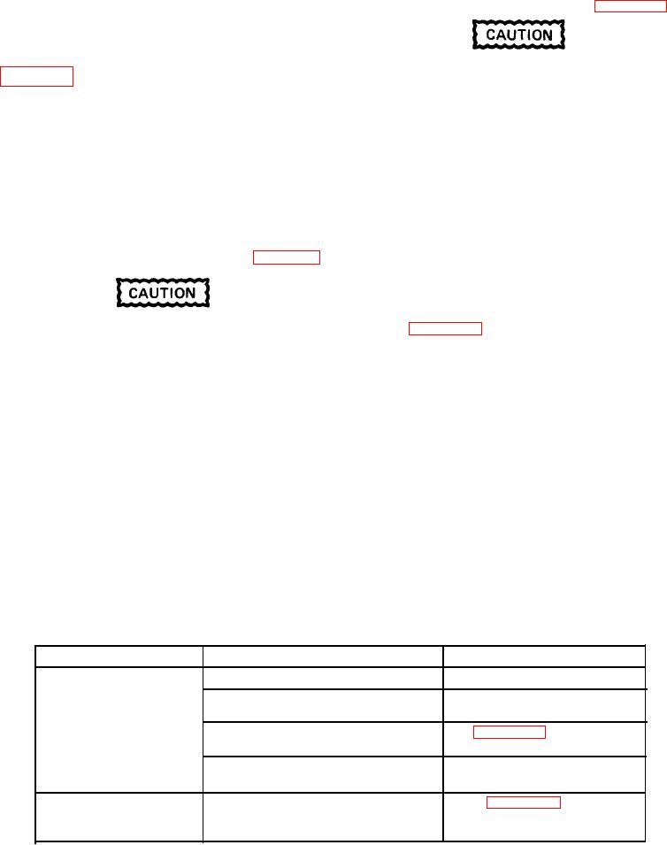
Table 5D-1. Troubleshooting Chart
REMEDY
PROBABLE CAUSE
TROUBLE
Disassemble, clean and flush.
Dirt in system.
Valve spool fails
to move.
Check electrical source and
Solenoids inoperative.
solenoids.
See Figure 5D-4 to check proper
Improper assembly after
assembly of unit.
overhaul.
Check installation.
Improper installation connec-
tion.
Check Figure 5D-4 for assembly
Improper assembly of valve or
Valve produces
and the schematic diagram in
improper installation con-
undesirable response
Subsection 5A for installation.
nections.
in work unit.
5D-5

