
SUBSECTION 6C
INTERMEDIATE SWING SHAFTS
GENERAL
This subsection covers the removal, disassembly, inspec-
tion, repair, assembly and installation of the intermediate
swing shaft. It is important to note that during assembly and
installation shims are used to adjust the bevel gear back-
lash with the swing clutch shaft bevel pinions.
INTERMEDIATE SWING SHAFT (9210JS0-3)
GENERAL. The intermediate swing shaft is mounted in the
revolving frame with the bevel gear in contact with the
swing clutch shaft pinions. The bevel gear, on the inter-
mediate swing shaft and the pinions on the swing clutch
shaft, are immersed in oil and continually lubricated.
REMOVAL AND DISASSEMBLY. Disassembly is accom-
plished during removal. To remove the intermediate swing
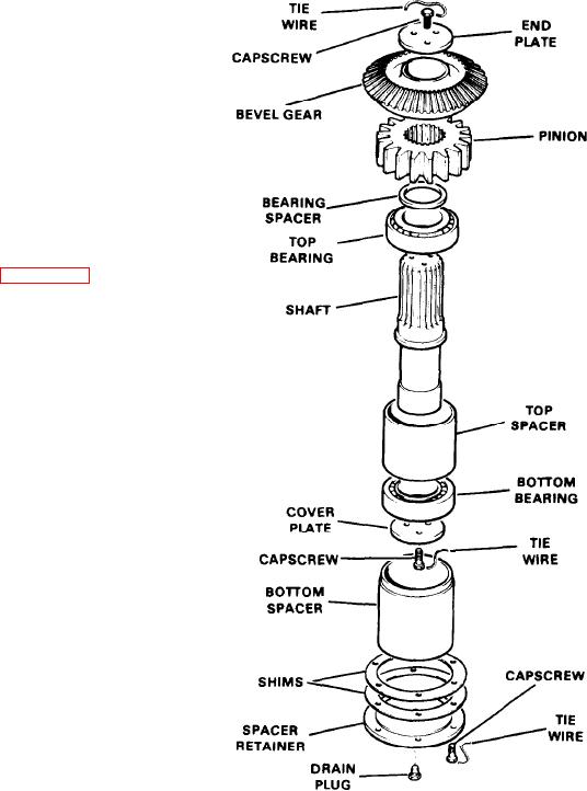
shaft, proceed as follows (see Figure 6C-1):
1. Drain the chain case and remove the chain case covers
on the front of the revolving frame.
2. Remove the horizontal swing shafts (see Subsection 6B).
3. Remove the end plate, then pull the bevel gear and
pinion from the shaft.
4. Attach an eyebolt to the shaft and lift the shaft and bear-
ings from the chain case bore.
NOTE
It is not necessary to remove the bottom spacer or
spacer retainer at this time.
5. Remove the cover plate by cutting the tie wire and re-
moving the capscrews.
6. Remove the bearing spacer and press the bearings off
the shaft.
INSPECTION AND REPAIR. Prior to assembly, all inter-
mediate swing shaft parts should be inspected as follows:
1. If the bevel gear or either of the swing pinions on the
swing clutch shaft are defective, replace all three gears. The
three gears tend to wear uniformly and the use of a com-
make backlash adjustments all but impossible.
2. Any bearing which shows any sign of wear or damage
should be replaced.
3 Replace all capscrews which have rounded corners and
all other damaged or worn parts.
Figure 6C-1. lntermediate Swing Shaft (9210J60-3)

