
PROPEL GEAR CASE
SUBSECTION 9D
ASSEMBLY
GENERAL. The propel gear case is assembled by section.
Each section is listed and the complete assembly proce-
dure for that section is given.
INPUT SECTION. To assemble the input section, proceedas
follows (see Figure 9D-12):
NOTE
used in the exact order in which they were removed. If
gears or bushings are replaced or if shim sets are lost
or damaged, the procedures listed below for deter-
mining shim requirements must be followed exactly.
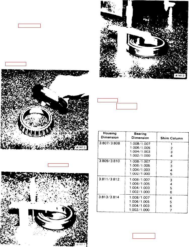
1. Place bearing cone (66) and cup (65) on a surface plate
(see Figure 9D-3).
Figure 9D-5. Depth Gauge
3. Determine the housing dimension from input housing
(57). This number is stamped on the mounting face (see
4. Refer to Table 9D-1 and, using the housing dimension
and bearing dimension previously obtained, determine the
shim column number.
Table 9D-1. Shim Column Determination
Figure 9D-3. Bearing Measurement
2. Measure the thickness of the bearing using a height
gauge or depth micrometer (see Figure 9D-4 and 9D-5).
5. Determine the gear mounting dimension by inspecting
gear (68) as shown in Figure 9D-7.
6. Refer to Table 9D-2 and, using the gear mounting di-
mension and shim column number, determine the total
Figure 9D-4. Height Micrometer
amount of shim distance required.
9D-3

