
REFINISH LAPPING BLOCKS. As the
continued use of the lapping blocks will
cause worn or low spots to develop in
their lapping surfaces, they should be
refinished from time to time.
It is good practice, where considerable
lapping work is done, to devote some
time each day to refinishing the blocks.
The quality of the finished work depends
to a great degree on the condition of the
lapping surfaces of the blocks.
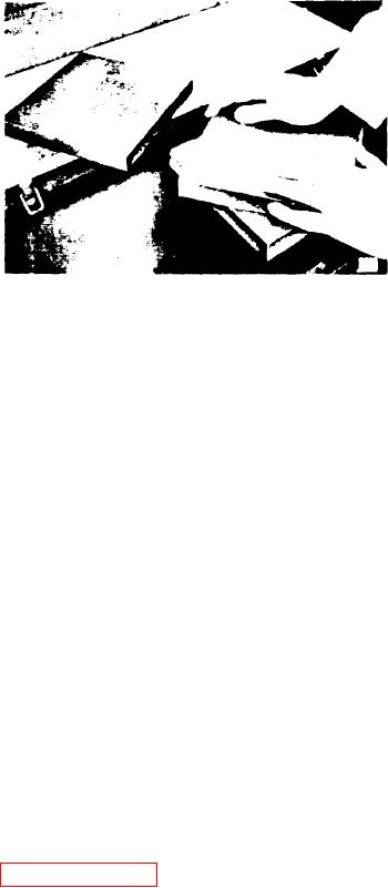
To refinish the blocks, spread some 600
grit lapping powder of good quality on
one of the blocks. Place another block
on top of this one and work the block to-
Figure 11C-75. Refreshing Lapping
gether as shown in Figure 11C-75. Al-
ternate the blocks from time to time. For
example, a s s u m i n g t h e b l o c k s a r e n u m -
output, any difference between the cali-
bered 1, 2 and 3, work 1 and 2 together,
brator and the masters should be used to
then 1 and 3, and finish by working 2
compute new injector calibration. If
and 3 together. Continue this procedure
more than a 2% variation from the mas-
until all of the blocks are perfectly flat
ters is noted, consult the calibrator
and free of imperfections.
manufacturer for possible causes.
Imperfections are evident when the
The calibrated masters should only be
blocks are clean and held under a strong
used to qualify injector output cali-
light. The blocks are satisfactory when
bration test equipment.
the entire surface is a solid dark grey.
Bright or exceptionally dark spots indi-
INJECTOR TIMING If it is suspected
cate defects and additional lapping is
that a fuel injector is "out of time", the
required.
injector rack-to-gear timing may be
checked without disassembling the injec-
After the surfaces have been finished,
tor.
remove the powder by rinsing the lap-
ping blocks in trichloroethylene and
A hole located in the injector body, on
scrubbing with a bristle brush.
the side opposite the identification tag,
may be used to visually determine wheth-
When not in use, protect the lapping
er or not the injector rack and gear are
blocks against damage and dust by stor-
correctly timed. When the rack is all the
ing them in a close fitting wooden con-
way in (full-fuel position), the flat side
tainer.
of the plunger will be visible in the hole,
indicating that the injector is "in time".
MASTER INJECTOR CALIBRATING KIT.
If the flat side of the plunger does not
Use Master Injector Calibrating Kit J
come into full view and appears in the
26298 to determine the accuracy of the
"advanced" or "retarted" position posi-
injector calibrator.
tion, disassemble the injector and correct
the
rack-to-gear
timing
(see
With the test fluid temperature at 100oF
Figure 11C-76 on page 11C-48).
1 (38C 1) and each injector warm
after several test cycles, run the three
INJECTOR SPRAY TIPS. Due to a slight
injectors contained in the kit. Several
variation in the size of the small orifices
readings should be taken with each injec-
in the end of each spray tip, the fuel
tor
to
check
for
accuracy
and
output of an injector may be varied by
repeatability. If the output readings are
replacing the spray tip.
within 2% of the values assigned to the
F l o w gauge J 25600 may be used to select
calibrated master, the calibrator can be
a spray tip that will increase or decrease
considered accurate.
fuel injector output for a particular in-
jector after it has been rebuilt and test-
injector testing can be carried out now
ed on the calibrator.
without any adjustment of figures. How-
ever, when testing new injectors for
11C-47
Fuel System and Governor

