
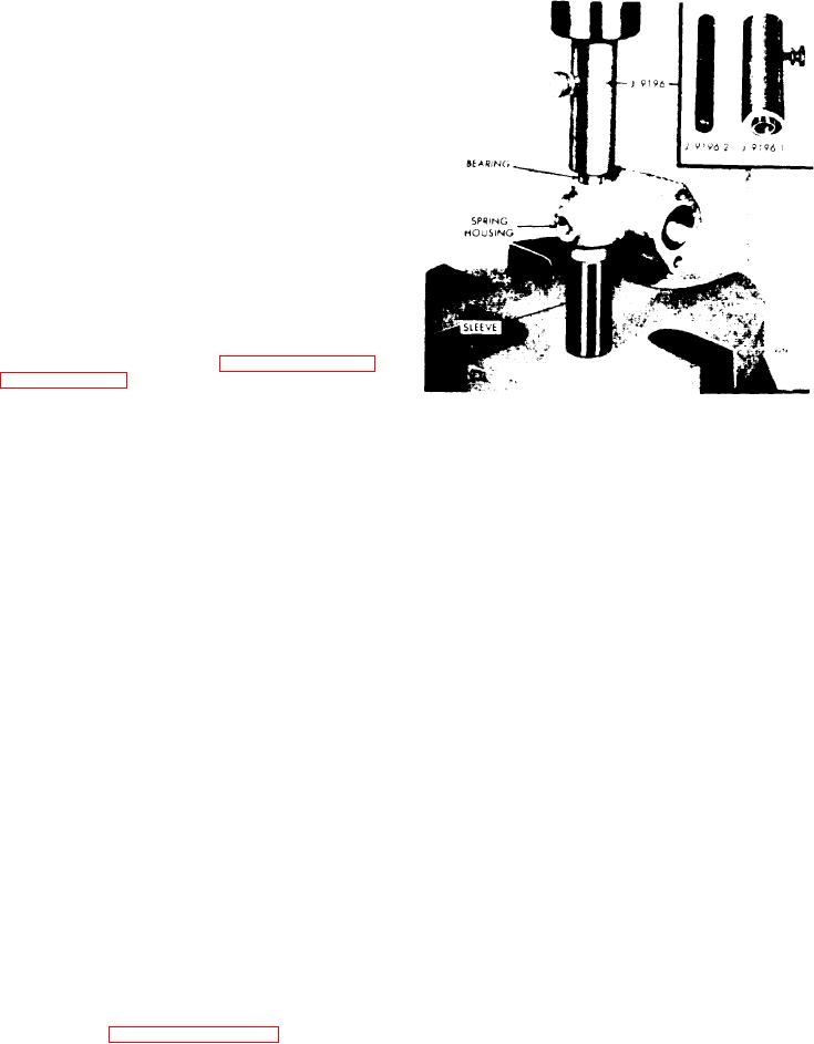
8. Remove the bearing pilot rod J9196-2
from installer body J 9196-1 and place
the installer body over the end of the
shaft and against the bearing. Support
the spring housing, bearing and installer
on a short sleeve on the bed of an arbor
press as shown in Figure 11C-73, then
press the bearing in the housing until
the shoulder on the installer contacts the
housing.
9. If a single lever shaft was installed in
the spring housing, apply a thin coat of
sealing compound to the outside diameter
of the cup plug. Start the cup plug
straight in the bearing bore in the hous-
ing, then support the spring housing,
bearings and shaft assembly on a sleeve
on the bed of an arbor press, and press
the cup plug in flush with the outside
face of the housing (see Figure 11C-71
Figure 11C-73. Installing Speed
10. Clamp the spring housing assembly
Control Shaft Bearings
in a bench vise equipped with soft jaws.
Then tighten the spring lever retaining
2.
Place
the
spring
retainer
in
the
set screw to 5-7 lb-ft (7-10 Nm) torque.
spring housing, with the closed end of
the retainer against the spring lever. If
11.
Stake the edge of the spring lever
shims were used, place them inside of
set
screw hole with a small center punch
the spring retainer. Insert the split
and
hammer to retain the set screw in
stop in the spring housing and against
the
lever.
the spring retainer.
12. On a single lever shaft, place a seal
ring over the end of the shaft and push
NOTE
it into the bearing bore and against the
Be
sure
to
use
shims
with
an
bearing. Place the plain washer over the
0.344" inside diameter. Either
shaft and against the housing, then in-
spring retainer may be used with
stall the Woodruff key in the keyway in
shims which have a 0.750" I.D..
the shaft.
However, do not use the 0.344"
I.D. shims with a spring retainer
13.
Place the speed control lever(s) on
w h i c h has only one air bleed hole.
the
shaft in its original position. Align
the
keyway in the lever with the key in
the
shaft and push the lever in against
3. Insert the variable speed spring in
the
plain washer and secure it in place
the spring plunger with the tightly
with
the retaining bolt and lock washer.
wound end of the spring against the
shims.
14. If removed, thread the lock nut on
the idle speed adjusting screw. Then,
4. Insert the bolts through the spring
thread the idle speed adjusting screw in-
housing. Place a new gasket over the
to the spring housing cover approximate-
bolts and against the housing.
ly 1".
5. Place the spring housing in position
against the control housing with the
A s s e m b l e Variable Speed Spring Housing
spring plunger engaged in the end of the
i n Control Housing
variable speed spring. Thread the bolts
in the control housing and tighten them
1.
Refer
to
on
page
securely.
11C-43 and insert the small end of the
spring plunger in the plunger guide.
Insert the solid stop in the governor
control housing.

