
NOTE
When the shoulder on the installer
body contacts the housing, the
bearing will be properly positioned
in the housing.
3. If removed, install the spring lever
Woodruff key in the center keyway in the
speed control lever shaft.
4. Place the spring lever assembly be-
tween the bearing bores inside the
spring housing with the arm (roller end)
of the lever facing out.
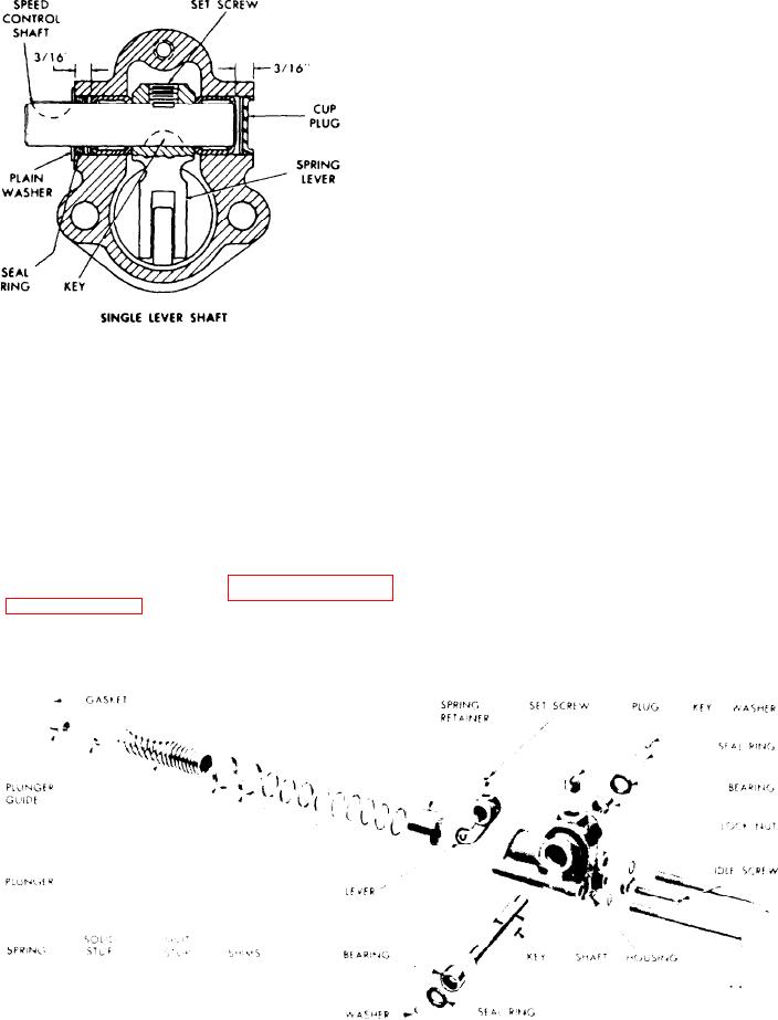
5. Insert the correct end of the single
lever type, speed control lever shaft
(Figure 11C-71) through the bearing
bore in the side of the spring housing,
opposite the bearing previously
Figure 11C-71. Cross Section of
installed. Align the key in the shaft
G o v e r n o r Variable Speed Spring
with the keyway in the spring lever, and
Housings
push the shaft through the lever and in
the bearing until the flat on the top of
Install the needle bearing pilot rod J
the shaft is centered under the set screw
hole in the lever.
9196-2 in the installer body J 9196-1 and
secure it in place with the retaining
screw.
6. Thread the set screw into the spring
lever, make sure the point of the screw
2. Place the pilot rod end of the bearing
is seated in the flat on the shaft.
installer assembly in the bearing. Sup-
port the spring housing, bearing and in-
7. Place the second speed control lever
staller on a short sleeve on the bed of an
shaft needle bearing, numbered end up,
over the protruding end of the shaft and
arbor press as shown in Figure 11C-73
on page 11C-44, then press the bearing
start it straight in the bore of the hous-
ing.
in the housing until the shoulder on the
installer contacts the housing.
Figure 11C-72. Variable Speed Spring Housing Details
Fuel System and Governor

