TM 10-3950-206-12
performance with that of a new coil.
c. Installation. Install the ignition coil in re- verse of
instructions for removal.
4-26. Distributor Assembly
a. General. The distributor is mounted on the right
side of the engine and is driven by a gear on the
camshaft. One of the distributor functions is to interrupt
the current flow through the primary winding of the
ignition coil, thus causing the coil to produce voltage high
enough to jump the gap at the spark plugs at the desired
instant during the compression stroke. As engine speed
increases, the spark must occur earlier at the spark
plugs. This is accomplished by an automatic spark
advance that is controlled by centrifugal weights in the
distributor. This is necessary to allow the fuel air mixture
sufficient time to ignite and burn. The centrifugal weights
advance the breaker cam to give a predetermined
variation in spark advance for different engine speeds.
An accurate measurement of ignition timing at any given
engine rpm can only be determined on the engine by use
of a timing light.
b. Removal.
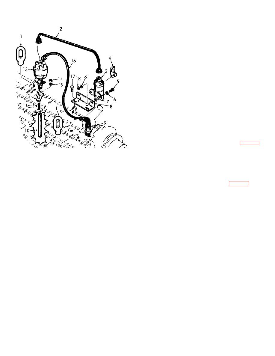
(1) Remove the spark plug wires (16, fig. 4-10)
and coil wire (2) from the top of the distributor (13).
Note. Tag al holes and wires to insure
ME 3950-206-12/4-10
correct installation.
(2) Remove nut (14), lockwasher (15), and
1. Lifting eye (2)
camp (12). Lift distributor assembly (13) from cylinder
2. Coil wire
head.
3. Coil
c. Disassembly.
4. Capacitor
(1) Remove screws (1 and 2, fig. 4-11) and
5. Capscrew (2)
distributor cap (3) from the housing (12).
6. Lockwasher (4)
(2) Remove rotor (5) from the shaft (9) and
7. Washer (2)
remove carbon button (4) and oil wick (6) from the rotor.
8. Bracket
(3) Remove screw (24) and contact assembly
9. Spark plug (6)
(23) from the breaker plate (22).
10. Drive shaft
(4) Remove screw (28) and bracket (26) from
11. Stud
breaker plate (22). Slide the condensor (27) out of the
12. Clamp
bracket (26).
13. Distributor
(5) Remove screws (25) breaker plate (22)
14. Nut
and holddown (20) from the housing (12). Remove
15. Lockwasher
screw (21) and lead (29) from the hold- down (20).
16. Wire assy (6)
(6) Disconnect springs (19) and remove
17. Capsrew (2)
springs and weights (8) and cam (18) from the shaft (9).
18. Nut (2)
(7) Remove pin (16), drive gear (17), shims
(15 and 14) and thrust washer (10) from the bottom of
Figure 4-10. Distributor, coil, plugs and wing, exploded
the shaft (9).
view.
(8) Remove shaft (9) from the housing (12),
and remove seal (11) and thrust washer (10) from the
(4) Remove two capscrews (17) and bracket
shaft (9).
(8) as required.
(9) Remove lube fitting (13) from the housing
b. Testing.
(12).
(1) If a coil tester is available, test the coil in
accordance with tester instructions.
(2) In the absence of a coil tester, compare
4-18


