TM 10-3950-206-12
(4) Loosen nut (7) and remove rod from clevis
shims.
(10) Remove nut from rod.
(3) Using a suitable puller remove the drive
(5) Remove cotter pin (9) and pin (13) to
yoke from the drive shaft.
remove clevis at rear of lever (12).
(4) Remove springs (4, fig. 4-51) and shoe and
(6) Remove cotter pin (9) and pin (13) to
lining assemblies (3) from the backing plate (1).
disengage clevis (10) at front of lever (17).
(5) Remove operating lever (5) and roller (2).
(7) Remove roll pin (11) which secures lever
(6) Remove four capscrews (13), lockwashers,
arm (12) to lever (17). Remove lever arm from lever.
(14), and backing plate (1).
c. Cleaning, Inspection and Repair.
Remove lever from lever support (1).
(8) Remove bolts (15) and lockwashers (16)
(1) Clean all metal parts with an approved cleaning
which secure lever support to transmission.
solvent and dry thoroughly with compressed air or a
(9) Loosen nut (7) and remove clevis (10) from
clean lint free cloth.
rod (14). Remove rod. Remove second nut from rod.
(2) Inspect the brake linings for excessive
(10) Remove cotter pin (9) and pin (13) and
wear, glazing or any other visual damage and repair by
clevis (10) at brake assembly.
replacement.
b. Cleaning and Inspection.
(3) Inspect the springs for broken, cracked or
(1) Clean all parts with an approved cleaning
deformed condition. Replace any spring that is broken,
solvent and dry thoroughly.
weak or otherwised damaged.
d. Assembly and Installation.
(2) Inspect all parts for damage or broken
welds.
(1) Assemble the parking brake and drive yoke
(3) A defective lever assembly (3) will have to
in reverse of the disassembly, paragraph b above.
be cut off of the seat support with a cutting torch.
(2) Install the transmission drive yoke and
(4) Replace any defective or damaged parts.
parking in reverse of removal.
c. Installation. Reverse procedures in a. above.
d. Adjustment. When adjusted, parking brake must
be capable of holding crane on a 15 percent grade with a
full, rated load.
(1) In order to draw brakeshoes closer to the
drum, the adjusting knob cap must be turned clockwise.
This shortens the stroke of adjusting tube assembly.
(2) If further adjustment is needed, turn adjusting
knob cap counterclockwise until stroke of adjusting tube
assembly is lengthened as much as possible.
(3) Remove pin from clevis and loosen nut on
tension rod. This enables the clevis to take up on
tension rod.
(4) Replace pin and take up adjusting tube
assembly with adjusting knob cap as much as is required
for final adjustment.
4-66. Parking Brake
a. General. The parking brake is an internal,
expanding shoe-type, mounted on the rear output of the
transmission. The shoe assembly back plate is bolted to
the transmission rear housing. The brake is a 13 3/8 x 2
inch size and is manually operated.
b. Removal and Disassembly.
(1) Disconnect the propeller shaft from the
transmission drive yoke (para 4-60).
(2) Remove eight self-locking capscrews and
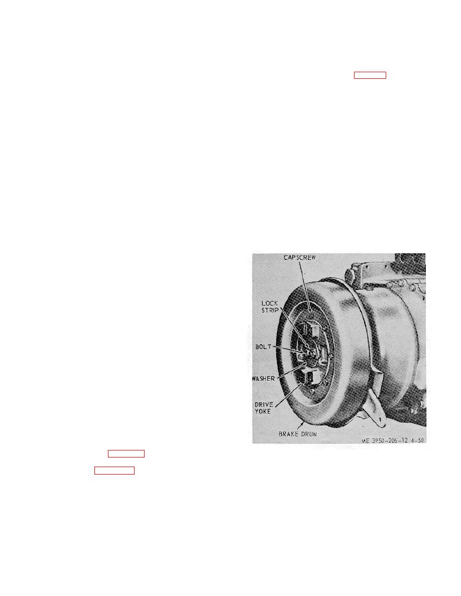
Figure 4-50. Brake drum, installed view.
brake drum, refer to figure 4-50, also flatten the lockstrip
and remove the flange bolts, lockstrip, washer and
4-53


